
Refrigerant recovery apparatus

By introducing the residual refrigerant recovery path and the auxiliary heat exchanger interface into the refrigerant recovery device, the problem of residual refrigerant in the auxiliary heat exchanger is solved, the refrigerant recovery efficiency and operating efficiency are improved, and the operation process is simplified.

Active Publication Date: 2020-03-06
DAIKIN INDUSTRIES LTD
View PDF10 Cites 2 Cited by
  • Summary
  • Abstract
  • Description
  • Claims
  • Application Information

AI Technical Summary

Problems solved by technology

Therefore, the operator needs to prepare water or ice cubes, put them in an insulated container, and transport them to the site before the refrigerant recovery operation, which is a major cause of increased man-hours and costs.
In addition, if the refrigerant recovery operation is performed on a plurality of refrigerant recovery machines 20 in one day, it is necessary to perform complicated operations such as replenishing water or ice cubes in the middle of the operation.

Method used


Image

  • Refrigerant recovery apparatus
  • Refrigerant recovery apparatus
  • Refrigerant recovery apparatus

Examples


Deformed example 1

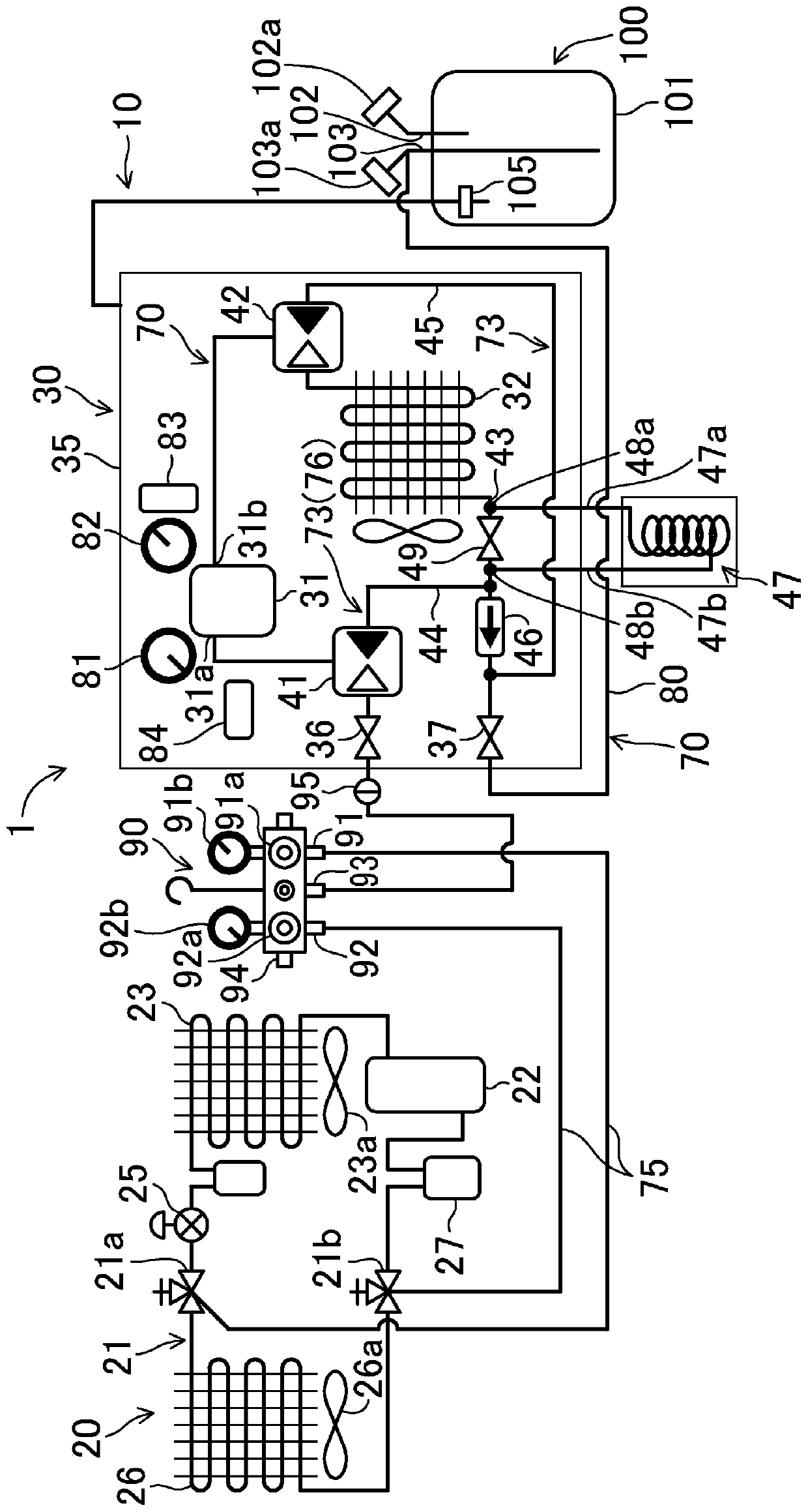
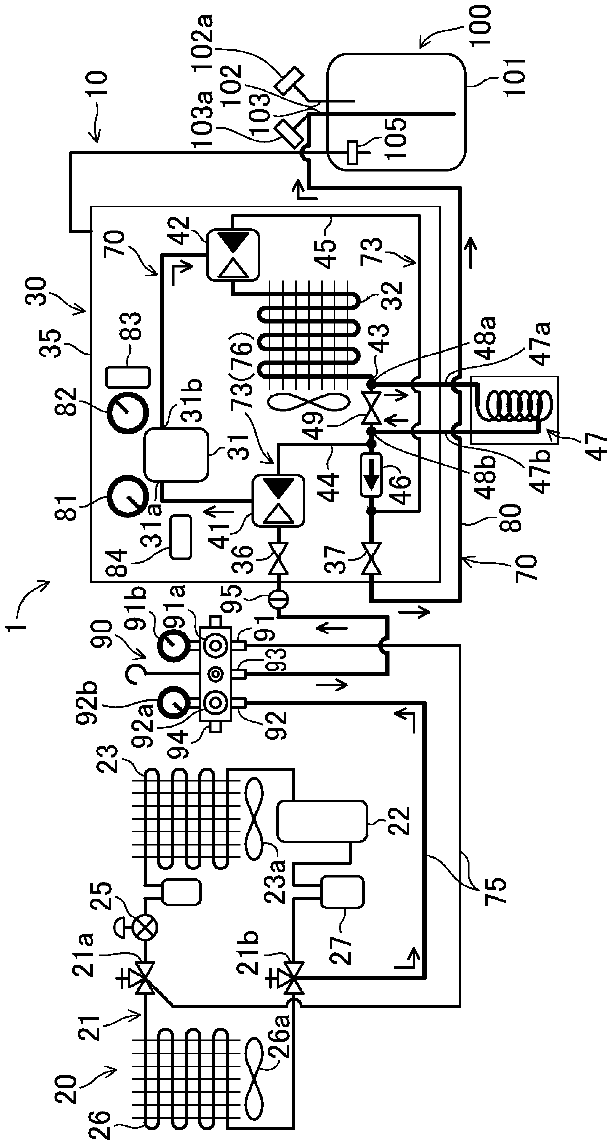
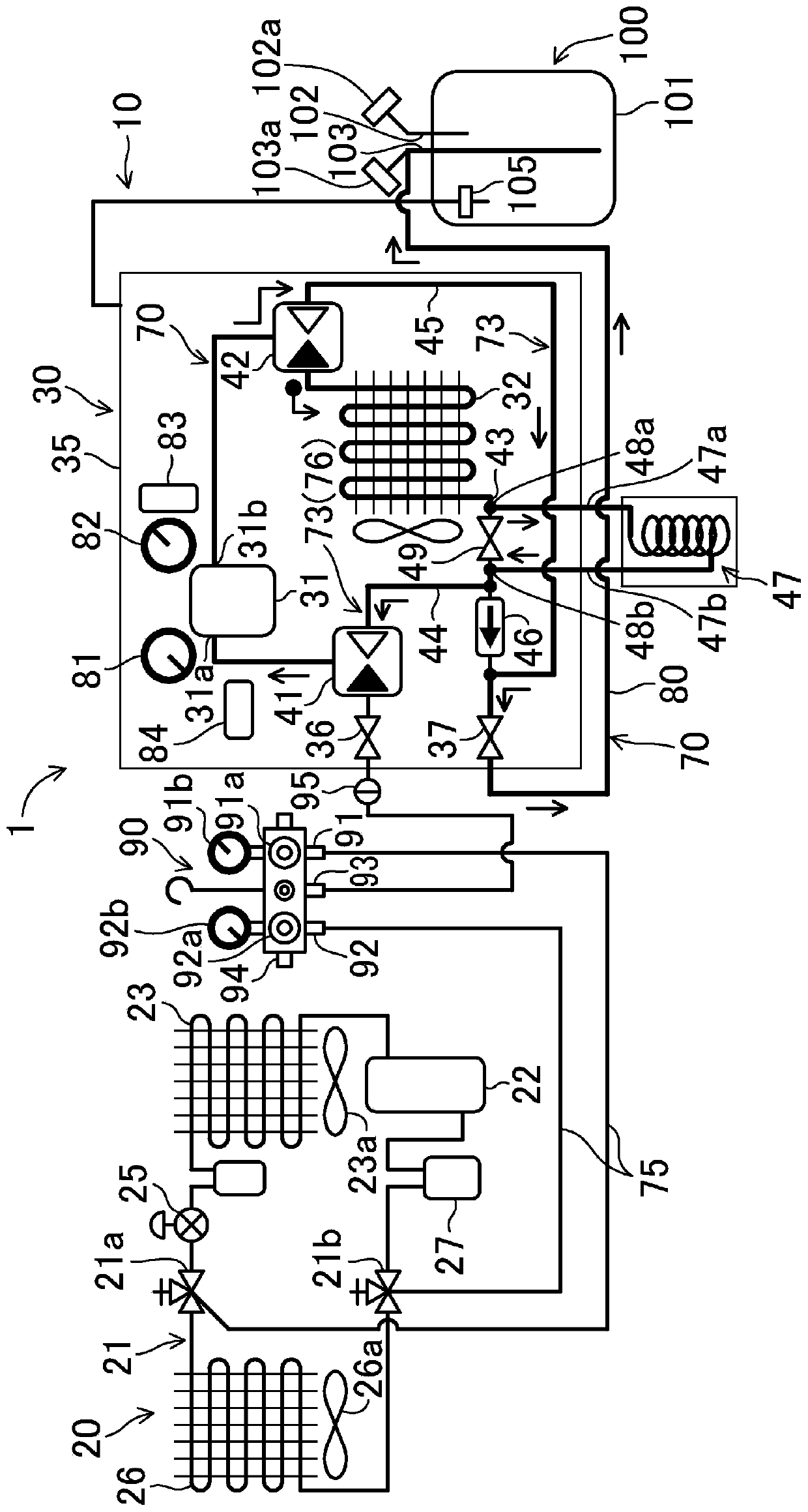
[0084] exist Figure 1 ~ Figure 3 In the embodiment, on the outlet pipe 43 of the condenser 32 and on the upstream side of the branch point of the main refrigerant recovery path 70 and the branch path 76, an auxiliary heat exchanger 47 that can be connected to the auxiliary heat exchanger 47 for cooling the refrigerant is provided. The auxiliary heat exchanger 47, which is a component different from the refrigerant recovery device 10, is connected to the auxiliary heat exchanger ports 48a, 48b. However, it is also possible to directly connect the auxiliary heat exchanger 47 to the outlet pipe 43 of the condenser 32 and the upstream side of the branch point of the main refrigerant recovery path 70 and the branch path 76, so that the auxiliary heat exchanger 47 is connected to the cooling system. The agent recovery device 30 is an integral part.

[0085] Even with the above structure, it is possible to receive figure 1 The implementation of the same effect.

Deformed example 2

[0087] The outlet pipe 43 of the condenser 32 can be constructed as Figure 4 , Figure 5 As in Modification 2 shown, the auxiliary heat exchanger 47 can be attached to the refrigerant recovery device 30 and can be detached from the refrigerant recovery device 30 . Figure 4 It is a figure which shows the state which removed the auxiliary heat exchanger 47 from the refrigerant recovery apparatus 30, Figure 5 It is a diagram showing a state in which auxiliary heat exchanger 47 is mounted on refrigerant recovery device 30 .

[0088] In this modified example 2, two connection joints 50a, 50b are provided on the outlet pipe 43 of the condenser 32 . The state where the auxiliary heat exchanger 47 is not used at the time of refrigerant recovery is Figure 4 In the state, the connection pipe 51 is installed between the two connection joints 50a, 50b. On the other hand, when the auxiliary heat exchanger 47 is used for refrigerant recovery, the Figure 4 After the shown connection ...


PUM


Abstract

The present invention provides a refrigerant recovery apparatus comprising a compressor (31) which intakes refrigerant from a device (20) containing refrigerant to be recovered and a condenser (32) which sends the refrigerant discharged from the compressor (31) to a refrigerant recovery container (100) via a main refrigerant recovery path (70), wherein: a residual refrigerant recovery path (77) isprovided in which the pressure of residual refrigerant from the condenser (32) is decreased within a branch path (76) which branches off from the main refrigerant recovery path (70), the compressor (31) intakes the residual refrigerant and pressurizes the same, and the residual refrigerant is sent to the refrigerant recovery container (100); and a cooling coil is connected on the outlet side of the condenser (32) upstream of the point where the main refrigerant recovery path (70) and the branch path (76) diverge.

Description

technical field [0001] The present disclosure relates to a refrigerant recovery device that sucks refrigerant from a refrigerant circuit of a refrigerant-recovered machine such as a refrigerator or an air conditioner, liquefies the refrigerant, and sprays the refrigerant to a container for recovering the refrigerant. out. Background technique [0002] Hitherto, in the case of repairing the parts constituting the refrigerant circuits of air conditioners and refrigerators after failure, or when moving or dismantling the air conditioners and refrigerators, etc., these air conditioners and refrigerators (refrigerating machines) Refrigerant recovery machine) for refrigerant recovery. The refrigerant recovery device and the refrigerant recovery container are connected with the refrigerant recovered machine to form a refrigerant recovery system, and the refrigerant recovery is carried out (for example, refer to Patent Document 1 Figure 5 ). [0003] Such as Figure 6 As shown, ...

Claims


Application Information

Patent Timeline
Patent Type & Authority Applications(China)
IPC IPC(8): F25B45/00
CPCF25B45/00F25B2345/002
Inventor 道明伸夫
Owner DAIKIN INDUSTRIES LTD
Learn More