Ultrasonic energy transducing equipment and ultrasonic transducer

An ultrasonic transducer and array technology, which is applied in ultrasonic/sonic/infrasonic diagnosis, ultrasonic therapy, ultrasonic/sonic/infrasonic Permian technology, etc., can solve the problems of limited depth, troublesome and time-consuming, and personal safety hazards of maintenance personnel.

Pending Publication Date: 2020-03-10
SHENZHEN INST OF ADVANCED TECH
View PDF0 Cites 6 Cited by
  • Summary
  • Abstract
  • Description
  • Claims
  • Application Information

AI Technical Summary

Problems solved by technology

However, in the process of entering the stomach, it must pass through the esophagus, and the diameter of the esophagus is only 15mm at the narrowest point, which greatly limits the actual size of the traditional ultrasonic transducer probe with invariable shape and size.
Ultimately limiting the depth of endoscopic imaging and endoscopically based in vivo HIFU therapy
[0006] In the industrial field, for the detection of the internal structure of some sealed chambers that are only connected by pipes, it is troublesome and time-consuming to open the chamber and reseal the operation, and the operation may have certain risks; while the non-destructive testing technology that enters through the connected pipes will inevitably bring more serious problems. Large and convenient, but the size of the pipe is smaller than that of the cavity, so a flexible and variable ultrasonic probe needs to be designed to adapt to pipes of different sizes
[0007] And in the industrial field, in some special environments, such as non-destructive testing of the internal environment of a closed cavity connected by pipelines with radiation, toxic gas liquid, volatile liquid gas, etc., when it is necessary to open the closed device, through the pipeline Entering into the cavity to realize detection is easy to cause harm to the personal safety of maintenance personnel

Method used


Image

  • Ultrasonic energy transducing equipment and ultrasonic transducer
  • Ultrasonic energy transducing equipment and ultrasonic transducer
  • Ultrasonic energy transducing equipment and ultrasonic transducer

Examples


Embodiment Construction

[0065] The invention discloses an ultrasonic transducer, which satisfies the imaging requirements of small-sized environments; the invention also provides an ultrasonic transducer device.

[0066] The technical solutions in the embodiments of the present invention will be clearly and completely described below in conjunction with the accompanying drawings in the embodiments of the present invention. Obviously, the described embodiments are only some, not all, embodiments of the present invention. Based on the embodiments of the present invention, all other embodiments obtained by persons of ordinary skill in the art without making creative efforts fall within the protection scope of the present invention.

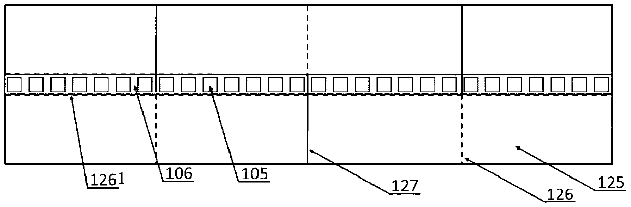
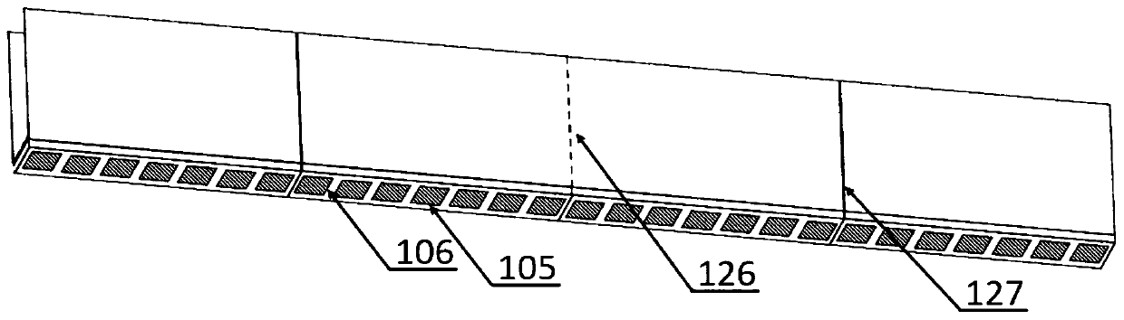
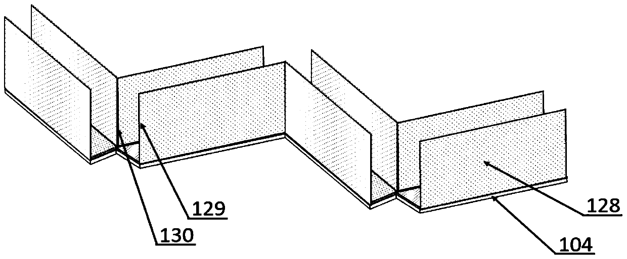
[0067] Such as Figure 1-Figure 5 as shown, figure 1 It is a schematic diagram of the cutting structure of the flexible circuit board of the ultrasonic transducer in the present invention; figure 2 for figure 1 Schematic diagram of the folding structure of the flexible ...


PUM


Abstract

The invention provides an ultrasonic transducer and ultrasonic energy transducing equipment. An ultrasonic transducer array module is supported by a backing block, an electric connection structure cansimultaneously transmit working power to a plurality of ultrasonic transducer array modules to ensure the supply of the working power, a conversion driving device is arranged on the backing block toprovide folding or unfolding of the backing block in the width direction of the backing block, a plurality of ultrasonic transducer array modules are arranged in the length direction in the folding process, the folding direction of adjacent ultrasonic transducer array modules in the deformation process changes directions alternately, and the elongated structure is deformed into a matrix structurearranged in parallel to meet the imaging requirement. Through the shape transformation of the ultrasonic transducer array module, the ultrasonic transducer array module can be transported in a long strip shape to meet the transportation requirements of small apertures; the long strip shape only has imaging capability, meets imaging requirements after matrix deformation, ensures imaging capabilityof the ultrasonic transducer, and also has HIFU treatment capability.

Description

technical field [0001] The invention relates to the technical field of ultrasonic imaging, and more specifically, to an ultrasonic transducer device and an ultrasonic transducer. Background technique [0002] In recent years, ultrasonic transducers based on piezoelectric materials have been widely used in the fields of biomedical imaging detection and disease treatment, industrial non-destructive flaw detection, and ocean detection. Especially in the field of biomedical health detection and disease treatment, in terms of imaging, compared with XRD ray detection, it has the advantages of being non-invasive and not potentially inducing other injuries, such as in gastric diseases, liver cirrhosis, intestinal diseases, pancreas Cancer, heart disease detection and other fields; in terms of disease treatment, HIFU (High-Intensity Focused Ultrasound, High-Intensity Focused Ultrasound) treatment technology based on high-intensity focused ultrasound, such as the treatment of female b...

Claims


Application Information

Patent Timeline
Patent Type & Authority Applications(China)
IPC IPC(8): B06B1/06A61B8/08A61B8/00A61N7/02
CPCA61B8/085A61B8/4483A61N7/02A61N7/022B06B1/0607
Inventor 马腾刘项力郑海荣黄继卿李永川王丛知刘佳妹杨晔
Owner SHENZHEN INST OF ADVANCED TECH
Why Eureka
Try Eureka