Combined three-phase common-body electronic current and voltage transformer

A voltage transformer, electronic current technology, applied in the direction of inductors, transformers/inductor shells, transformers, etc., can solve the shielding effect, poor anti-interference ability, difficult to meet high-performance testing, difficult to obtain uniform internal electric field distribution, etc. problem, to achieve the effect of good self-cleaning performance, great practical and popularization value, and uniform distribution of the internal electric field

Inactive Publication Date: 2020-03-10
南京新宁光电工程有限公司
View PDF0 Cites 3 Cited by
  • Summary
  • Abstract
  • Description
  • Claims
  • Application Information

AI Technical Summary

Problems solved by technology

An electronic current and voltage transformer is currently disclosed. Although this structure significantly reduces the overall weight, due to the structure, it is difficult to obtain a uniform distribution of the internal electric field, and its shielding effect and anti-interference ability are poor. , it is difficult to meet the requirements of high-performance testing, so it is necessary to improve the existing combined electronic current and voltage transformers to improve the use effect of the equipment

Method used


Image

  • Combined three-phase common-body electronic current and voltage transformer
  • Combined three-phase common-body electronic current and voltage transformer
  • Combined three-phase common-body electronic current and voltage transformer

Examples


Embodiment Construction

[0016] The following will clearly and completely describe the technical solutions in the embodiments of the present invention with reference to the accompanying drawings in the embodiments of the present invention. Obviously, the described embodiments are only some, not all, embodiments of the present invention.

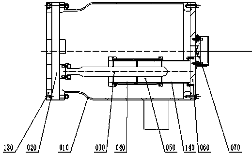
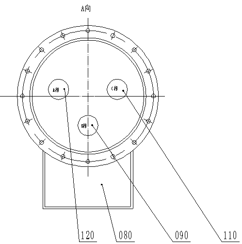
[0017] The upper positioning flange (130) is fixed on the upper half of the housing (010); the basin insulator (020) is connected with the housing (010); the primary conductive rod (030) is connected to the basin insulator ( 020) conductors are connected; the current coil shielding tube (040) is fixed on the lower positioning flange (060); the current coil (050) is arranged around the current coil shielding tube (040); three sets of primary conductive rods ( 090, 110, 120), the current coil shielding cylinder (040), and the current coil (050) are evenly distributed in the casing (010) to form a three-phase electronic current transformer; a shielding is provided on the...


PUM


Abstract

The invention relates to a combined three-phase common-body electronic current and voltage transformer. The transformer is composed of a shell, a primary conducting rod, a current coil shielding cylinder, a current coil, a shielding cylinder, a grounding electrode, a basin-type insulator, an explosion-proof sheet and the like. An upper positioning flange is fixedly installed on an upper half partof the shell. The primary conducting rod is connected with a conductor of the basin-type insulator. A current coil shielding cylinder is fixedly arranged on a lower positioning flange. A current coilis arranged at a periphery of the current coil shielding cylinder. The shielding cylinder is arranged at the periphery of the primary conducting rod, one end of the shielding cylinder is connected with the primary conducting rod, and the other end is insulated from the primary conducting rod. Because a current transformer and a voltage transformer are combined into one body, a whole machine is compact in structure and small in size; because the shell, the shielding cylinder, the primary conducting rod and the electrode are made of aluminum alloy with a low expansion coefficient, and each portis designed to be arc-shaped, point discharge is reduced, and an internal electric field is uniform.

Description

technical field [0001] The invention relates to an electronic transformer used in the electric power industry, in particular to a combined three-phase communal electronic current and voltage transformer. Background technique [0002] Existing high-voltage transformers are mainly divided into voltage transformers and current transformers. High-voltage current transformers are further divided into oil-immersed current transformers and sulfur hexafluoride current transformers. Due to structural reasons, oil-immersed current transformers and sulfur hexafluoride current transformers generally have iron cores, and electromagnetic induction is used to convert data. This type of current transformers uses iron cores, so magnetic saturation occurs. The electromagnetic induction ability is obviously reduced, and the volume is large, so that the overall weight is obviously heavier. Although the existing electronic current transformers and voltage transformers overcome the defects of l...

Claims


Application Information

Patent Timeline
Patent Type & Authority Applications(China)
IPC IPC(8): H01F27/02H01F27/28H01F27/30H01F27/36H01F38/34
CPCH01F27/02H01F27/28H01F27/30H01F27/36H01F38/34
Inventor 曹金根孙志杰姚康
Owner 南京新宁光电工程有限公司
Why Eureka
Try Eureka