
Special conveyor for degradable occluder

A technology of occluder and conveyor, which is applied in the field of medical equipment, can solve the problems of occluder implantation, etc., and achieve the effect of round front end, convenient operation, and simple and convenient operation process

Pending Publication Date: 2020-03-13
JIANGSU BRIGHTNESS MEDICAL DEVICES
View PDF0 Cites 1 Cited by
  • Summary
  • Abstract
  • Description
  • Claims
  • Application Information

AI Technical Summary

Problems solved by technology

[0004] The purpose of the present invention is to provide a special transporter for a degradable occluder, which solves the problem of how to implant the occluder into the lesion defect in the prior art, and realizes a transporter with transport and locking functions. device

Method used


Image

  • Special conveyor for degradable occluder
  • Special conveyor for degradable occluder
  • Special conveyor for degradable occluder

Examples


Embodiment 1

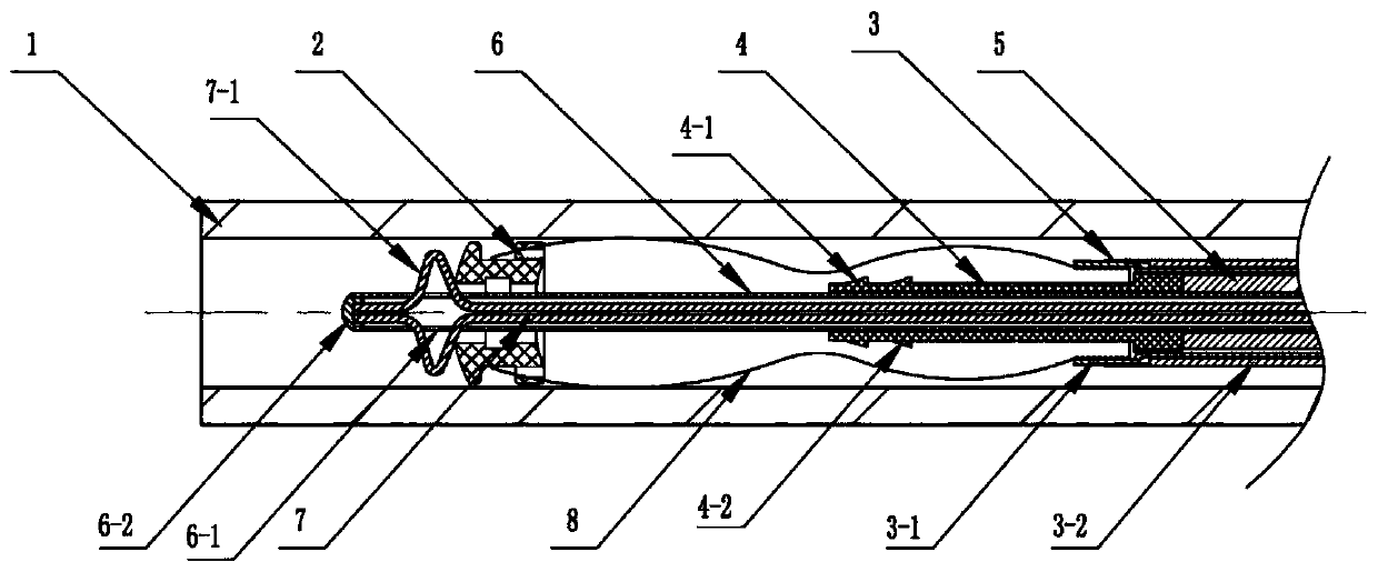
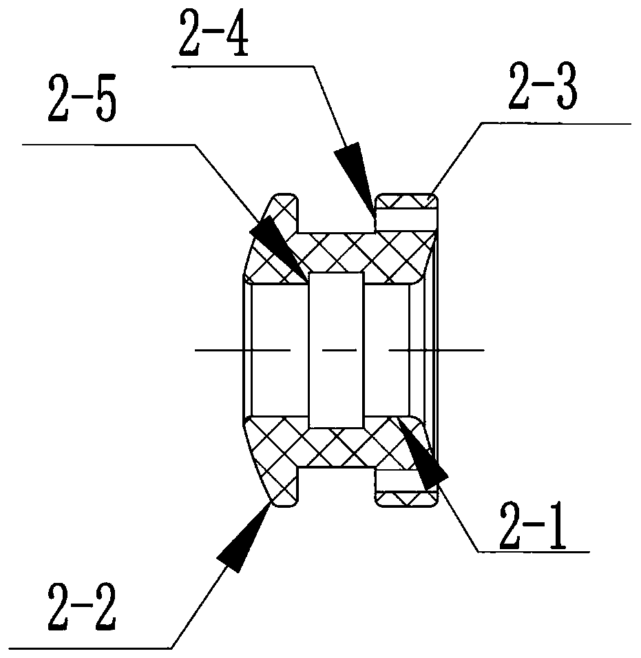
[0053] Such as Figure 1 to Figure 5 A special conveyor for a degradable occluder is shown, including: a sheath tube 1, a cap 2, a clamping device 3, a lock 4, a positioning rod 5, a pull rod outer tube 6, a pull rod 7, and a degradable occluder 8.

[0054] Such as figure 1 As shown, the cap 2 , the clamping device 3 , and the degradable occluder 8 are all arranged in the sheath tube 1 . The head of the degradable occluder 8 is fixedly connected to the cap 2, and the tail is connected to the clamping device 3; the front and middle parts of the lock 4 are inserted into the degradable occluder 8 from the tail of the degradable occluder 8, The rear part is set in the tightening device 3; the front part of the positioning rod 5 is set in the tightening device 3, and its front end surface is in contact with the rear end surface of the lock buckle 4; 4. The degradable occluder 8 and the cap 2; the tie rod 7 is arranged in the outer tube 6 of the tie rod.

[0055] Such as figur...

Embodiment 2

[0066] The structure of embodiment 2 is similar to that of embodiment 1, except that the structure of the outer tube 6 of the tie rod is different. Such as Figure 10 The outer tube 6 of the pull rod shown in Embodiment 2 is a braided outer tube, which includes a PTFE tube layer, a metal braided wire tube layer, and a PA / PU tube layer from the inside to the outside. The braided outer tube has strong tensile strength and a PTFE tube inside. Layer, smooth inner wall, good lubricity, easy to penetrate, accurate positioning.

Embodiment 3

[0068] Embodiment 3 is similar in structure to Embodiment 1, except that the structure of the fastening tube 3-1 is different. Such as Figure 11 and Figure 12 The fastening tube 3-1 of the shown embodiment 3 has four notches at the front end, so that the front end of the fastening tube 3-1 is more elastic than that of the first embodiment, and the head is designed in a tooth shape, which is convenient and degradable for plugging Device 8 is tightly combined.


PUM


Abstract

The invention discloses a special conveyor for a degradable occluder. The special conveyor comprises a sheath pipe, a cap, a clamping device, a lock catch, a positioning rod, a pull rod outer pipe anda pull rod. The degradable occluder is arranged in the sheath pipe and is fixedly connected with the cap through compilation. The front part and the middle part of the lock catch penetrate through the degradable occlude from its tail part, the front part is provided with a clamping part suitable for clamping with the cap, and a rear part is arranged in the clamping device. The front side wall ofthe pull rod outer pipe is provided with a through hole. The front part of the pull rod is provided with a deformation part which penetrates out of the through hole at the front end of the pull rod outer pipe. By adopting the structural design, the position of the occluder in the conveying process can be limited, and the separation of the auxiliary occluder from the conveyor can be realized. The operation is convenient. By combining the transportation and locking functions of the degradable occlude, one product can realize two functions, so that the operation process is simple and convenient.

Description

technical field [0001] The invention relates to the field of medical devices, in particular to a special conveyor for a degradable occluder. Background technique [0002] The number of patients with congenital heart disease is increasing every year. In the past, the treatment of these diseases required surgical thoracotomy and open-heart surgery. The damage is large, the cost is expensive, and sometimes surgical complications and large surgical scars are left, causing long-term physical and psychological trauma to patients. Therefore, people try to replace surgical operation by medical interventional therapy. In 1967, Porstmann first used non-surgical interventional therapy to perform foam sponge embolization on the incomplete ductus arteriosus of congenital heart disease, creating a precedent for interventional therapy of congenital heart disease, but the success rate was not high. In the 1990s, American radiologists invented a mushroom-shaped occluder made of memory allo...

Claims


Application Information

Patent Timeline
Patent Type & Authority Applications(China)
IPC IPC(8): A61B17/12
CPCA61B17/12022A61B2017/1205
Inventor 吴新张文娟
Owner JIANGSU BRIGHTNESS MEDICAL DEVICES
Learn More