Log debarking device for wood processing

A log and lumber technology, applied in the field of log debarking devices for wood processing, can solve the problems of high processing cost, affect operation, consume a lot of manpower and material resources, and achieve the effects of reducing workload, improving safety, and improving work efficiency.

Pending Publication Date: 2020-03-13
张振远
View PDF7 Cites 7 Cited by
  • Summary
  • Abstract
  • Description
  • Claims
  • Application Information

AI Technical Summary

Problems solved by technology

[0003] At present, the existing tree peeling method is generally a hand electric planer, which consumes a lot of manpower and material resources, and requires frequent maintenance, high processing costs, and affects the stable operation of the work. Therefore, it is urgent to design a log peeling machine for wood processing. device to solve the above problems

Method used


Image

  • Log debarking device for wood processing
  • Log debarking device for wood processing
  • Log debarking device for wood processing

Examples


Embodiment 1

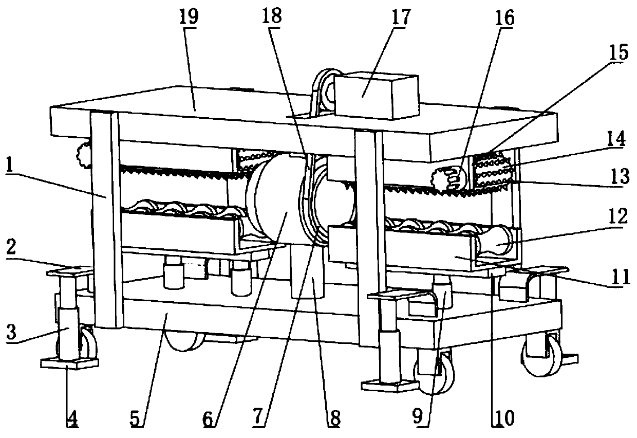
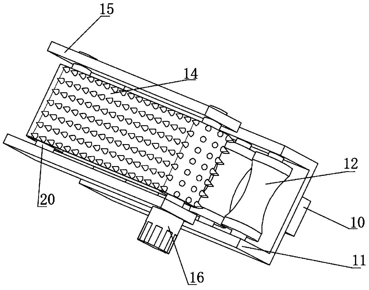
[0026] Reference Figure 1-3 , A log peeling device for wood processing, comprising an upper mounting plate 19 and a lower mounting plate 5. The top outer wall of the lower mounting plate 5 is equipped with first electric telescopic rods 9 on both sides, and two first electric telescopic rods 9 on the top outer wall The same first fixing plate 10 is installed, the top outer wall of the first fixing plate 10 is installed with a connecting frame 11, and the inner walls of the two ends of the connecting frame 11 are rotatably connected with arc-shaped squeezing rollers 12 distributed at equal distances, and the bottom outer wall of the upper mounting plate 19 A second fixing plate 15 is installed on both ends of the two second fixing plates 15 and the outer walls of the opposite ends of the two second fixing plates 15 are rotatably connected to both sides of the rotating shaft 20, and the outer wall of the two rotating shafts 20 is sleeved with the same conveyor belt 14 , The outer...

Embodiment 2

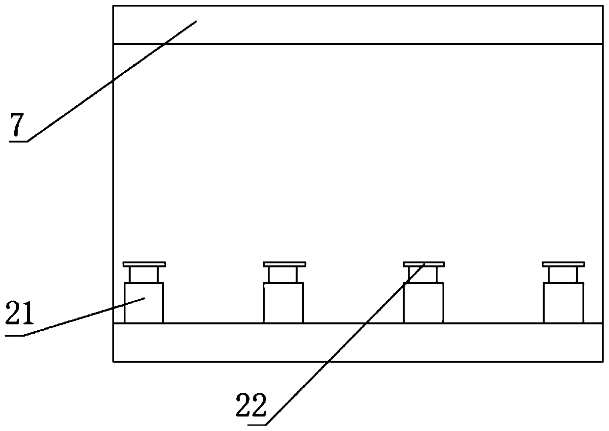
[0030] Reference Figure 1-4 , A log peeling device for wood processing, further comprising a first fixed plate 10 and a connecting frame 11 fixedly connected to the first fixed plate 10 and the connecting frame 11 provided with a sliding block 23, the top outer wall of the sliding block 23 is connected to the connecting frame by bolts 11 The bottom outer wall is fixedly connected, the top outer wall of the first fixing plate 10 is provided with a sliding groove, the bottom outer wall of the sliding block 23 is equipped with equidistantly distributed telescopic springs 24, and the bottom outer wall of the telescopic spring 24 is fixedly connected to the bottom inner wall of the first fixed plate 10 by bolts .

[0031] Working principle: Compared with Embodiment 1, the sliding block 23 and the telescopic spring 24 can be provided to fix the log more firmly, avoid unevenness of the log surface and damage the device, and improve the safety of the device.


PUM


Abstract

The invention discloses a log debarking device for wood processing. The device includes an upper mounting plate and a lower mounting plate, first electric telescopic rods are installed on two sides ofthe top outer wall of the lower mounting plate, and a same first fixing plate is installed on the top outer walls of the two first electric telescopic rods; a connecting frame is installed on the topouter wall of the first fixing plate, and the inner walls of two ends of the connecting frame are rotatably connected with equidistantly distributed arc-shaped pressing rollers; second fixing platesare installed at two ends of two sides of the bottom outer wall of the upper mounting plate, and rotating shafts are rotatably connected to two sides of the outer walls of the opposite ends of the twosecond fixing plates; and a same conveyer belt sleeves the circumferential outer wall of the two rotating shafts. According to the device, a servo motor is arranged, a mounting ring can be driven torotate by a transmission belt, the position of scrapers on second electric telescopic rods can be adjusted to scrape bark of the surface of logs, so that the working efficiency is improved, and the workload of workers is reduced.

Description

Technical field [0001] The invention relates to the technical field of wood processing, in particular to a log peeling device for wood processing. Background technique [0002] Wood is the lignified tissue formed by plants capable of secondary growth, such as trees and shrubs. After the primary growth of these plants is over, the vascular cambium in the rhizome begins to move, develops bast outwards and wood inwards. Furniture has become an indispensable thing in people’s lives, and the material used to make furniture is wood, so trees need to be processed. For wood processing, the wood needs to be peeled before the veneer is peeled to make the wood Better use. [0003] At present, the existing wood peeling method is generally a flashlight planer, which requires a lot of manpower and material resources, and requires frequent maintenance, high processing costs, and affects the stable operation of the work. Therefore, it is urgent to design a log peeling for wood processing. Devic...

Claims


Application Information

Patent Timeline
Patent Type & Authority Applications(China)
IPC IPC(8): B27L1/00
CPCB27L1/00
Inventor 张振远
Owner 张振远
Why Eureka
Try Eureka