
Active resistance-capacitance DC current limiter and control method based on dual capacitor oscillation

A control method and current limiter technology, applied in emergency protection circuit devices for limiting overcurrent/overvoltage, usage of superconductor elements, electrical components, etc., can solve the difficulty of operation and maintenance, and the cost of active DC current limiters Expensive and other issues, to achieve the effect of simple daily operation and maintenance, good current limiting effect, and energy saving

Active Publication Date: 2021-07-27
EXAMING & EXPERIMENTAL CENT OF ULTRAHIGH VOLTAGE POWER TRANSMISSION COMPANY CHINA SOUTHEN POWER GRID
View PDF4 Cites 0 Cited by
  • Summary
  • Abstract
  • Description
  • Claims
  • Application Information

AI Technical Summary

Problems solved by technology

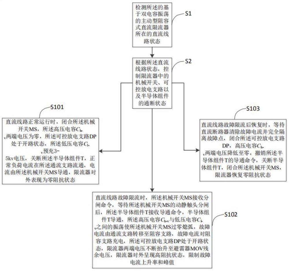
[0004] In view of the above problems, the present invention proposes an active resistance-capacitance DC current limiter and a control method based on dual-capacitor oscillation, which mainly solves the problems of high cost and difficult operation and maintenance of the active DC current limiter

Method used


Image

  • Active resistance-capacitance DC current limiter and control method based on dual capacitor oscillation
  • Active resistance-capacitance DC current limiter and control method based on dual capacitor oscillation

Examples


Embodiment Construction

[0023] In order to make the purpose, technical solution and advantages of the present invention more clear and definite, the content of the present invention will be further described in detail below in conjunction with the accompanying drawings and specific embodiments. It should be understood that the specific embodiments described here are only used to explain the present invention, but not to limit the present invention. In addition, it should be noted that, for the convenience of description, only parts related to the present invention are shown in the drawings but not all content.

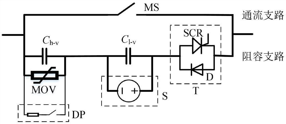
[0024] according to figure 1 As shown, this embodiment proposes an active RC-type DC current limiter based on dual-capacitor oscillation, including a parallel flow-through branch and a RC branch. The flow-through branch is composed of a mechanical switch MS. The resistance-capacitance branch is connected in series by the high-voltage arm capacitance branch, the low-voltage arm capacitance br...


PUM


Abstract

The invention discloses an active resistance-capacitance DC current limiter based on dual-capacitor oscillation and a control method thereof, which include a parallel flow-through branch and a resistance-capacitance branch, the flow-through branch is composed of a mechanical switch, and the resistance-capacitance branch is composed of a high-voltage arm The capacitor branch, the low-voltage arm capacitor branch and the semiconductor component are connected in series; the high-voltage arm capacitor branch includes a parallel high-voltage capacitor, an arrester, and a controllable discharge branch; the low-voltage arm capacitor branch includes a parallel low-voltage capacitor and a controllable charging power supply, and the semiconductor The component is composed of a thyristor and a diode in antiparallel connection, the negative pole of the low-voltage capacitor is electrically connected with the high-voltage capacitor, and the positive pole of the low-voltage capacitor is electrically connected with the anode of the semiconductor component. The beneficial effects of the present invention are: the current limiter in the present invention is mainly composed of conventional power equipment such as mechanical switches, high-voltage capacitors, low-voltage capacitors, thyristors and diodes, and the cost is low. At the same time, because no superconducting materials or power electronic devices are used, the limited The daily operation and maintenance of the flow meter is easier.

Description

technical field [0001] The invention relates to the technical field of power equipment, in particular to an active resistance-capacitance DC current limiter and a control method based on double-capacitor oscillation. Background technique [0002] Hybrid multi-terminal DC transmission system is an important part of my country's long-distance transmission system. After a short-circuit fault occurs in the hybrid multi-terminal DC transmission system, the voltage source converter will feed the fault current to the fault point. For the fault current component fed by the voltage source converter, its flow path has small damping, fast rising speed and Cannot be cleared quickly by controlling the inverter. The voltage source converter is mainly composed of fully-controlled power electronic devices (IGBT), and its ability to withstand surge current is weak. Therefore, this part of the fault current may damage key equipment such as the converter, and then pose a serious threat to the...

Claims


Application Information

Patent Timeline
Patent Type & Authority Patents(China)
IPC IPC(8): H02H9/02H02H3/087
CPCH02H3/087H02H9/02Y02E40/60
Inventor 王越杨彭光强何竞松李清武霁阳国建宝杨光源王海军
Owner EXAMING & EXPERIMENTAL CENT OF ULTRAHIGH VOLTAGE POWER TRANSMISSION COMPANY CHINA SOUTHEN POWER GRID
Learn More