Elastomer rubber seal ring drag reduction test device and elastomer rubber seal ring/non-smooth surface integrated drag reduction test device

A rubber sealing ring, non-smooth surface technology, applied in the field of drag reduction test devices, can solve the problems of inability to complete the model test, difficulty in daily maintenance, noise pollution, etc., and achieve the effect of convenient daily operation and maintenance, simple and reliable structure, and stable movement.

Inactive Publication Date: 2016-05-04
HARBIN ENG UNIV
View PDF4 Cites 0 Cited by
  • Summary
  • Abstract
  • Description
  • Claims
  • Application Information

AI Technical Summary

Problems solved by technology

The bionic non-smooth elastic surface can reduce the frictional resistance between the elastic body and the solid, and the drag reduction effect is obvious. It is a brand-new drag reduction technology, but the current research on this technology is mainly concentrated in the theoretical analysis and numerical simulation stage. There is not yet a complete set of test equipment for bionic non-smooth elastic surface resistance testing, so the model test cannot be completed
Traditional drag reduction test research is usually carried out in testing machines such as friction and wear testing machines. However, due to its high cost, high cost, difficulty in daily maintenance, serious noise pollution, and various aspects of test conditions have certain limitations. And it is impossible to study the drag reduction test of bionic non-smooth elastic surface

Method used


Image

  • Elastomer rubber seal ring drag reduction test device and elastomer rubber seal ring/non-smooth surface integrated drag reduction test device
  • Elastomer rubber seal ring drag reduction test device and elastomer rubber seal ring/non-smooth surface integrated drag reduction test device
  • Elastomer rubber seal ring drag reduction test device and elastomer rubber seal ring/non-smooth surface integrated drag reduction test device

Examples


Embodiment Construction

[0024] The present invention is described in more detail below in conjunction with accompanying drawing example:

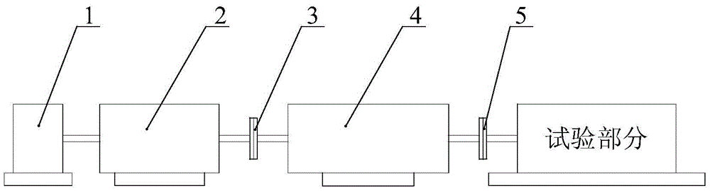
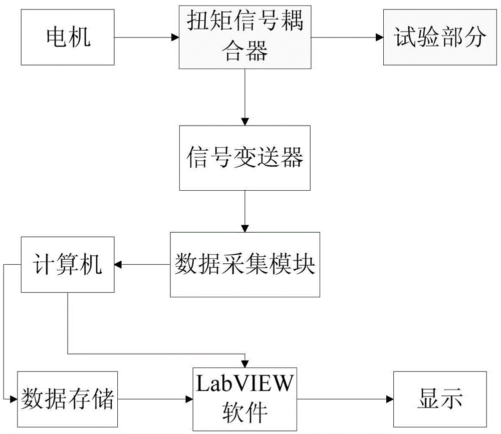
[0025] combine Figure 1-9, the structure of the present invention is mainly divided into three parts: a power part, a data measurement and acquisition part, and a test part, wherein the test part includes two test processes, that is, test process a and test process b. The test process a mainly realizes the friction resistance test of the ○-shaped rubber sealing ring with a non-smooth surface, while the test process b mainly realizes the drag reduction effect test of the test sample with a non-smooth surface. In the test process a, the frequency modulation motor 2 is used as the power source of the whole device, and under the control of the frequency converter 1, it provides rotational power for the whole test device. When the transmission shaft 11 is in a rotating state, it will drive the sample cover cup 18 at its end and the ○-shaped rubber sealing ring 17 fix...


PUM


Abstract

The invention aims to provide an elastomer rubber sealing ring drag reduction test device and an elastomer rubber sealing ring / non-smooth surface integrated drag reduction test device. A frequency converter, a frequency adjustment motor, a torque signal coupler and the left end of a transmission shaft are connected with one another in sequence; the right end of the transmission shaft is sleeved with a shaft sleeve; the transmission shaft is connected with the shaft sleeve through a flat key; the shaft sleeve is positioned in a test cavity; the test cavity is fixed on a device base; the middle part of the transmission shaft penetrates through the test cavity and is matched with the test cavity through cavity angular contact ball bearings; a sample piece sleeving cup is fixed outside the shaft sleeve; the sample piece sleeving cup is in clearance fit with the inner wall of the test cavity; an annular slot for mounting an elastomer rubber sealing ring is formed in the sample piece sleeving cup; the elastomer rubber sealing ring is in contact with the inner wall of the test cavity after being arranged in the annular slot. The elastomer rubber sealing ring drag reduction test device and the elastomer rubber sealing ring / non-smooth surface integrated drag reduction test device which are disclosed by the invention move steadily, and are simple and reliable in structure, controllable in pressure and convenient to mount and dismount.

Description

technical field [0001] The invention relates to a drag reduction test device, in particular to a drag reduction test device for an elastic body rubber sealing ring and a non-smooth surface. Background technique [0002] At present, relevant scholars at home and abroad have reached a certain level of research on the application of bionic non-smooth surface feature technology to reduce frictional resistance, and have successfully made significant progress in many aspects. Experts and scholars from various countries have applied the idea of ​​elastic non-smooth structure surface drag reduction and engineering bionics theory to the research of drag reduction on elastic non-smooth surfaces and metal surfaces in oil or gas media, and the drag reduction performance of pit-shaped non-smooth surfaces Analyze, develop an effective green drag reduction technology and develop ideas for product innovation, and provide a theoretical basis for the engineering and practical application of b...

Claims


Application Information

Patent Timeline
Patent Type & Authority Patents(China)
IPC IPC(8): G01N19/02G01L5/00
Inventor 赵刚谷云庆李照远刘文博赵健英李芳张殊刘明明汝晶赵华兴
Owner HARBIN ENG UNIV
Why Eureka
Try Eureka