High-efficiency thickener combining central transmission and sectional rake raising

A technology of central transmission and concentrator, which is applied in the field of concentrators, which can solve the problems of inability to turn over and easy scraping of mud scrapers, so as to achieve the effects of increasing efficiency, avoiding shaking and increasing work quality

Active Publication Date: 2020-03-17
安徽盛世开元装备科技有限公司
View PDF9 Cites 2 Cited by
  • Summary
  • Abstract
  • Description
  • Claims
  • Application Information

AI Technical Summary

Problems solved by technology

Moreover, most of the scrapers under the existing concentrator are fixed in the same direction and cannot be turned over. When rotating in one direction for a long time, the scraper is easy to scrape cleanly

Method used


Image

  • High-efficiency thickener combining central transmission and sectional rake raising
  • High-efficiency thickener combining central transmission and sectional rake raising
  • High-efficiency thickener combining central transmission and sectional rake raising

Examples


Embodiment 1

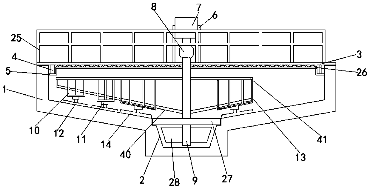
[0037] see Figure 1-9 , according to an embodiment of the present invention, a high-efficiency concentrator combined with a central drive and a segmented rake, comprising a concentration pool 1, a mud collection groove 2 is provided at the bottom of the center of the concentration pool 1, and a fixed device is installed on the concentration pool 1. There is a working bridge 3, a vertical plate 4 is arranged under the working bridge 3, a fixed groove 5 is fixedly arranged on the inner wall of the concentration tank 1, the vertical plate 4 is fixed in the fixed groove 5, and the working bridge 3 A bracket 6 is fixedly arranged on the bracket 6, and a motor 7 is fixedly arranged on the bracket 6. The output end of the motor 7 is provided with a motor reducer 8, and the output end of the motor reducer 8 is provided with a central main shaft 9. The center The main shaft 9 runs through the working bridge 3 and extends into the mud-collecting groove 2, and the outer wall of one end of...

Embodiment 2

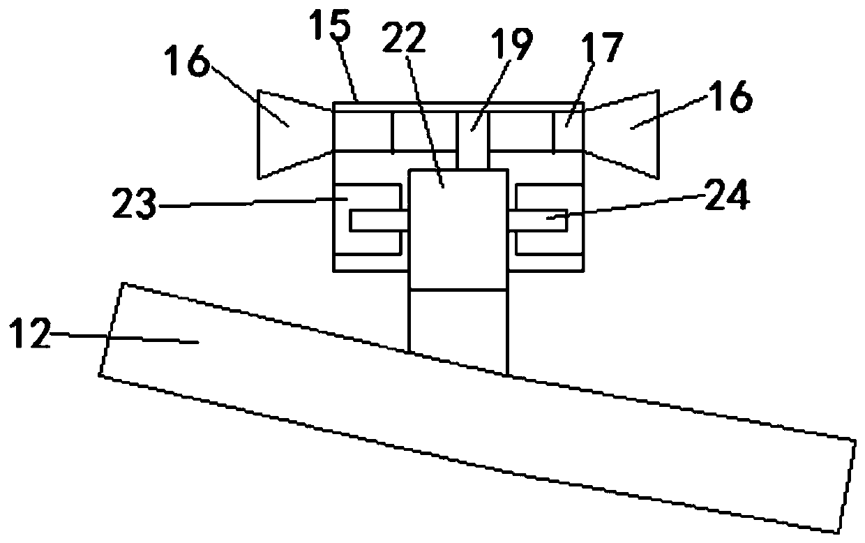
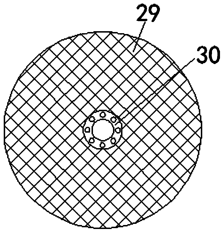
[0040] see Figure 8-9 , for the working bridge 3, railings 25 are fixed on both sides of the working bridge 3. As for the fixing slots 5 , an auxiliary frame 26 is fixed between the fixing slots 5 . For the underwater support assembly 27, the underwater support assembly 27 includes a first filter plate 29, the middle part of the first filter plate 29 is fixed with a bearing 30, and the inner wall of the bearing 30 is fixed with the central spindle 9 . As for the mud-collecting groove 2, a clamping groove is opened at the upper end of the mud-collecting groove 2, and the first filter plate 29 is fixed in the clamping groove. For the limit stop groove 23, the limit stop groove 23 includes an upper cover plate, a lower cover plate and a middle plate, and the middle plate is fixed between the upper cover plate and the lower cover plate, so The arc length of the middle plate is smaller than that of the upper cover plate and the lower cover plate, and the rotating baffle plate 2...

Embodiment 3

[0043] see Figure 1-9 , for the arc-shaped groove 18, the outside of the arc-shaped groove 18 is located inside the connecting cylinder 15, and a compression-resistant mechanism is provided. For the anti-pressure mechanism, the anti-pressure mechanism includes a liquid-through groove 31, the liquid-through groove 31 is located in the connecting cylinder 15 outside the arc-shaped groove 18, and the two ends of the liquid-through groove 31 pass through The vertical groove 32 is in communication with the water passage 17, and the second filter plate 33 is fixedly arranged in the vertical groove 32, and a vertical rod 34 is provided for moving in the second filter plate 33, and the vertical rod 34 is fixed at the bottom. A water blocking plate 35 is provided, and the water blocking plate 35 is adapted to the water passage 17. A spring 36 is set on the vertical rod 34, and the two ends of the spring 36 are respectively fixed on the second filter. On the plate 33 and the water blo...


PUM


Abstract

The invention discloses a high-efficiency thickener combining central transmission and sectional rake raising. The thickener includes a thickening tank. The center bottom of the thickening tank is provided with a mud collecting groove. A working bridge is fixedly arranged on the thickening tank. A vertical plate is arranged below the working bridge. A fixing groove is fixedly provided on the innerwall of the thickening tank. The vertical plate is fixed in the fixing groove. A bracket is fixed on the working bridge. A motor is fixed on the bracket. The output end of the motor is provided witha motor reducer, and the output end of the motor reducer is provided with a central spindle. The central spindle passes through the working bridge and extends into the mud collecting groove. Beneficial effects are that energy is reasonably utilized, settled materials are not liable to fly up, the work efficiency is increased, the working quality of second and third mud scrapers is improved, and coagulation of impurities difficult to clean at the bottom of the thickening tank is avoided.

Description

technical field [0001] The invention relates to the field of thickeners, in particular to a high-efficiency thickener combined with central drive and segmented rake lifting. Background technique [0002] At present, there are mainly three types of high-efficiency thickeners widely used in China: 1. Central drive, central rake thickener; 2. Peripheral drive, segmental rake thickener; 3. Peripheral drive center rake thickener; the third type That is, the center drive and center rake thickeners are more advanced, and it combines the advantages of the first two thickeners. [0003] However, because the material deposited near the central part of the concentration pool bottom is more than the peripheral part; and the material deposited in the peripheral part must be scraped toward the center, so the scraping efficiency of the central part of the concentrator is required to be higher than that of the peripheral part, and currently All thickeners have the same number of times of s...

Claims


Application Information

Patent Timeline
Patent Type & Authority Applications(China)
IPC IPC(8): B01D21/06B01D21/18B01D21/22B01D21/24
CPCB01D21/06B01D21/186B01D21/22B01D21/245
Inventor 宫开元刘秉承宫硕民刘力铭
Owner 安徽盛世开元装备科技有限公司
Why Eureka
Try Eureka