Roadway charging device, vehicle current collector device and vehicle mobile charging method
A charging device and power receiving device technology, which is applied to vehicle components, circuits, collectors, etc., can solve the problems of high cost of use, difficulty in vacating space, and poor convenience of use, and achieve low construction costs and ensure charging safety. Effect
- Summary
- Abstract
- Description
- Claims
- Application Information
AI Technical Summary
Problems solved by technology
Method used
Image
Examples
Embodiment 1
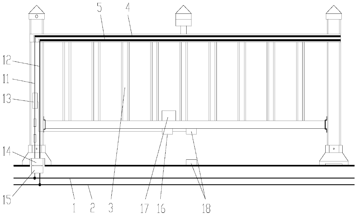
[0067] Embodiment 1, the roadway charging device of this embodiment includes a positive power transmission line 1 and a negative power transmission line 2 buried along the roadway.
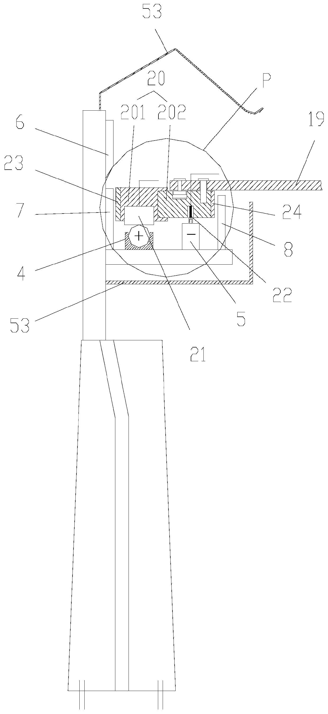
[0068] The roadway charging device of this embodiment also includes a road isolation frame 3 arranged along the roadway and a power supply provided on the road isolation frame for sliding contact with the receiver of the charging vehicle; The positive pole conductor 4 and the negative pole conductor 5 arranged in parallel, the positive pole conductor and the negative pole conductor are respectively connected with the positive pole power line and the negative pole power line buried along the roadway.
[0069] The power supply also includes a limiting structure for limiting the receiver moving along the positive conductor and the negative conductor, and the limiting structure is used to limit the distance range of the receiver moving left and right on the positive conductor and the negative conductor...
Embodiment 2
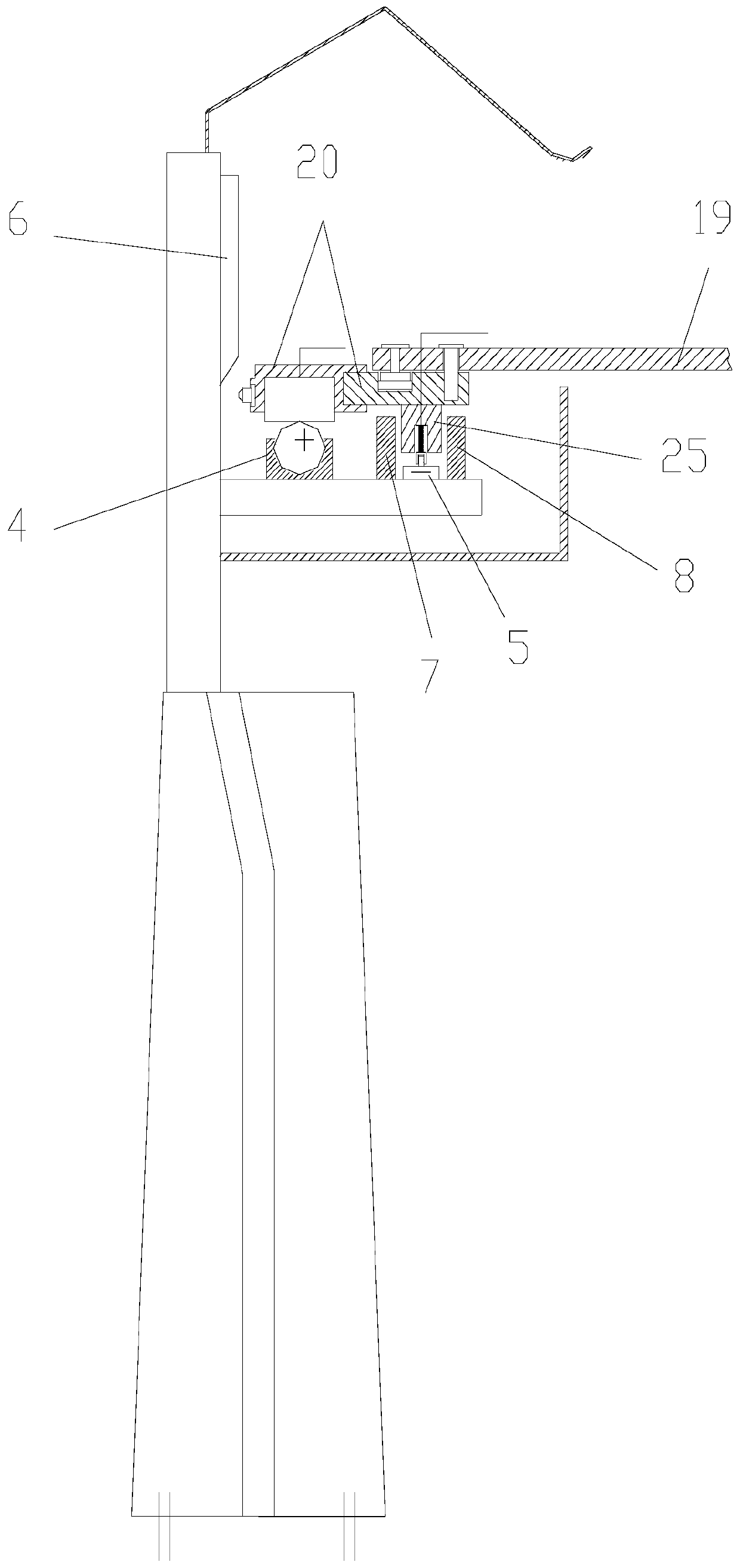
[0083]Embodiment 2, the power receiving device of the vehicle in this embodiment includes a lifting drive mechanism, a deflection drive mechanism, a swing arm 19, a swing arm locking mechanism and a power receiver. The positive current receiver 21 on the top and the negative current receiver 22 are arranged on the mounting seat, and the mounting seat is provided on one end of the swing arm. In a specific implementation, the mounting base can be composed of two parts: an insulator on which the positive current receiver is set and a rigid body on which the negative current receiver is set. The negative electrode receiver 22 can be composed of a sleeve 221, a sliding telescopic rod 222 arranged in the sleeve, a roller 223 arranged at the end of the sliding telescopic rod, and a spring 224 that is placed outside the sleeve to apply a thrust to the roller. Under the action of the spring, the roller can be reliably in contact with the negative electrode conductor, and of course the ...
Embodiment 3
[0108] Embodiment 3, the vehicle mobile charging method of this embodiment includes the following steps:
[0109] 1) Drive the deflection arm to deflect to the power supply through the deflection drive mechanism;
[0110] 2) When the receiver touches the vertical guide plate of the power supply, the lifting drive mechanism drives the swing arm to move down or up, so that the receiver moves vertically along the vertical guide plate, so that the limiter of the receiver and the power supply The limit structure of the electrical appliance is in a coordinated state; the lifting drive mechanism continues to drive the swing arm to move down or up, so that the positive conductor of the receiver and the positive conductor of the power supply are in charging contact state, and the negative receiver of the receiver It is in charging contact with the negative conductor of the power supply;
[0111] 3) At the end of charging, first drive the swing arm up or down through the lifting drive ...
PUM
 Abstract
Description
Claims
Application Information
 - R&D
- Intellectual Property
- Life Sciences
- Materials
- Tech Scout
- Unparalleled Data Quality
- Higher Quality Content
- 60% Fewer Hallucinations
Browse by: Latest US Patents, China's latest patents, Technical Efficacy Thesaurus, Application Domain, Technology Topic, Popular Technical Reports.
© 2025 PatSnap. All rights reserved.Legal|Privacy policy|Modern Slavery Act Transparency Statement|Sitemap|About US| Contact US: help@patsnap.com


