
Conveying device for prefabricated concrete

A technology of concrete prefabricated parts and conveying devices, applied in the direction of transportation and packaging, conveyor objects, etc., can solve the problems of reducing production efficiency and increasing production costs of enterprises, and achieve the effects of improving production efficiency, improving processing efficiency, and increasing yield

Active Publication Date: 2021-08-10
安徽晶宫绿建集团有限公司
View PDF8 Cites 0 Cited by
  • Summary
  • Abstract
  • Description
  • Claims
  • Application Information

AI Technical Summary

Problems solved by technology

[0003] In the construction industry, in the production process of concrete prefabricated parts, it is necessary to pour concrete into the mold with steel bars. First, the steel bars need to be set in the mold, and then the staff needs to put multiple prefabricated parts production molds side by side. It is placed at one end of the conveying device. At present, it is usually necessary to configure multiple workers. The workers are required to set the steel bars in the mold, and then the workers are required to place multiple prefabricated production molds on the conveying device in each production cycle. At one end, the staff also needs to walk back and forth to place the prefabricated part production molds in the corresponding positions and check them, which will increase the production cost of the enterprise and reduce the production efficiency

Method used


Image

  • Conveying device for prefabricated concrete
  • Conveying device for prefabricated concrete
  • Conveying device for prefabricated concrete

Examples


Embodiment Construction

[0021] In order to make the object, technical solution and advantages of the present invention clearer, the present invention will be described in further detail below in conjunction with specific embodiments and with reference to the accompanying drawings.

[0022] It should be noted that all expressions using "first" and "second" in the embodiments of the present invention are to distinguish two entities with the same name but different parameters or parameters that are not the same, see "first" and "second" It is only for the convenience of expression, and should not be construed as a limitation on the embodiments of the present invention, which will not be described one by one in the subsequent embodiments.

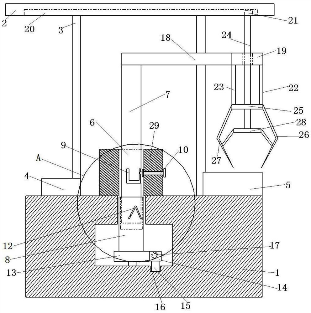
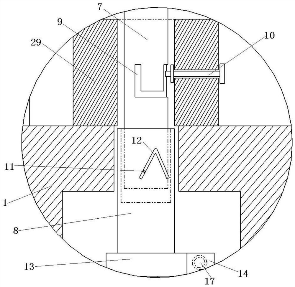
[0023] A conveying device for prefabricated concrete, comprising a conveying base 1, a first conveying platform 4 is arranged on the conveying base 1, a second conveying platform 5 is arranged on one side of the first conveying platform 4, the conveying base There is ...


PUM


Abstract

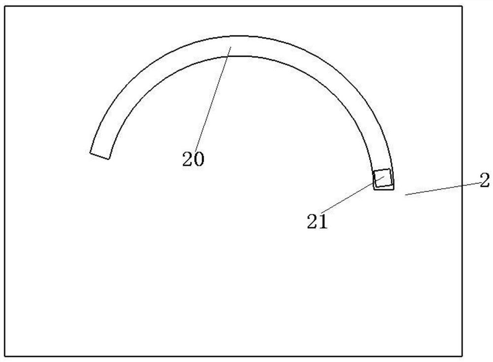
The invention discloses a conveying device for concrete prefabricated parts, comprising a conveying base, a first conveying platform is arranged on the conveying base, a second conveying platform is arranged on one side of the first conveying platform, and a rotating conveying mechanism is arranged on the conveying base , the rotating conveying mechanism includes a rotating rod, a limiting platform is arranged on the conveying base, the rotating rod passes through the limiting platform, the upper end of the rotating rod is connected with a fixed assembly through a connecting frame, a top plate connected by a supporting frame is arranged above the connecting frame, and a top plate is connected under the top plate An arc-shaped track is provided on the end surface, and a second sliding block is slidably connected in the arc-shaped track, and the lower end of the second sliding block is connected with the fixed component. In the present invention, a steel bar is placed on the first conveying platform, and a mold is placed on the second conveying platform, and the rotating conveying mechanism drives the steel bar wire clamped by the fixed assembly to move upwards, move toward the second conveying platform, and reach the second conveying platform After the upper part, the steel bar clamped by the fixed component is driven to move down and be placed in the mold, which improves the production efficiency.

Description

technical field [0001] The invention relates to the technical field of concrete prefabricated parts processing, in particular to a concrete prefabricated part conveying device. Background technique [0002] Concrete precast parts, also known as PC components, refer to concrete products that are processed and produced in factories through standardized and mechanized methods. Correspondingly, traditional cast-in-place concrete requires on-site molding, on-site pouring and on-site maintenance. Prefabricated concrete is widely used in construction, transportation, water conservancy and other fields, and plays an important role in the national economy. Such as prefabricated reinforced concrete column foundation, prefabricated steel structure steel column foundation, street lamp billboard column reinforced concrete foundation, prefabricated floor slab. [0003] In the construction industry, in the production process of concrete prefabricated parts, it is necessary to pour concre...

Claims


Application Information

Patent Timeline
Patent Type & Authority Patents(China)
IPC IPC(8): B65G47/90B65G47/52
CPCB65G47/52B65G47/901
Inventor 陆也
Owner 安徽晶宫绿建集团有限公司
Learn More