Device and method for detecting deformation stress of on-site cement-based material

A cement-based material, deformation stress technology, applied in the direction of measuring devices, material inspection products, analytical materials, etc., can solve the problems of high requirements for concrete deformation stress detection accuracy, influence of civil engineering construction quality, lack of test devices and methods, etc. The acquisition method is simple and direct, the detection data is comprehensive and reliable, and the detection structure is simple and reasonable.

Pending Publication Date: 2020-03-17
HARBIN INST OF TECH
View PDF0 Cites 5 Cited by
  • Summary
  • Abstract
  • Description
  • Claims
  • Application Information

AI Technical Summary

Problems solved by technology

It is difficult to quantitatively detect the shrinkage (frost heave) stress of cement-based materials under high temperature, normal temperature or negative temperature environment
In short, due to the high precision requirements, difficulty, low efficiency, and poor accuracy of concrete de

Method used


Image

  • Device and method for detecting deformation stress of on-site cement-based material
  • Device and method for detecting deformation stress of on-site cement-based material
  • Device and method for detecting deformation stress of on-site cement-based material

Examples


specific Embodiment approach 1

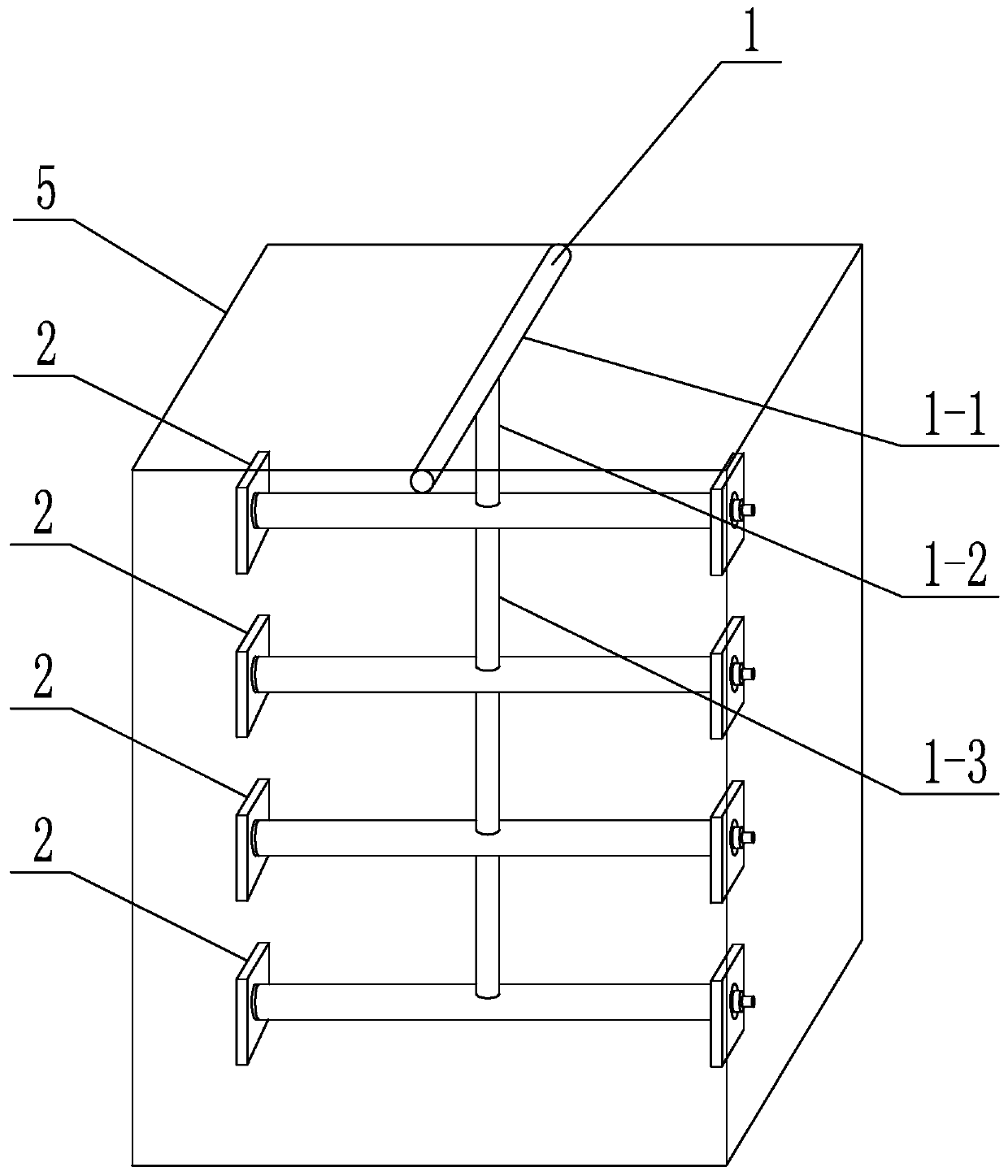
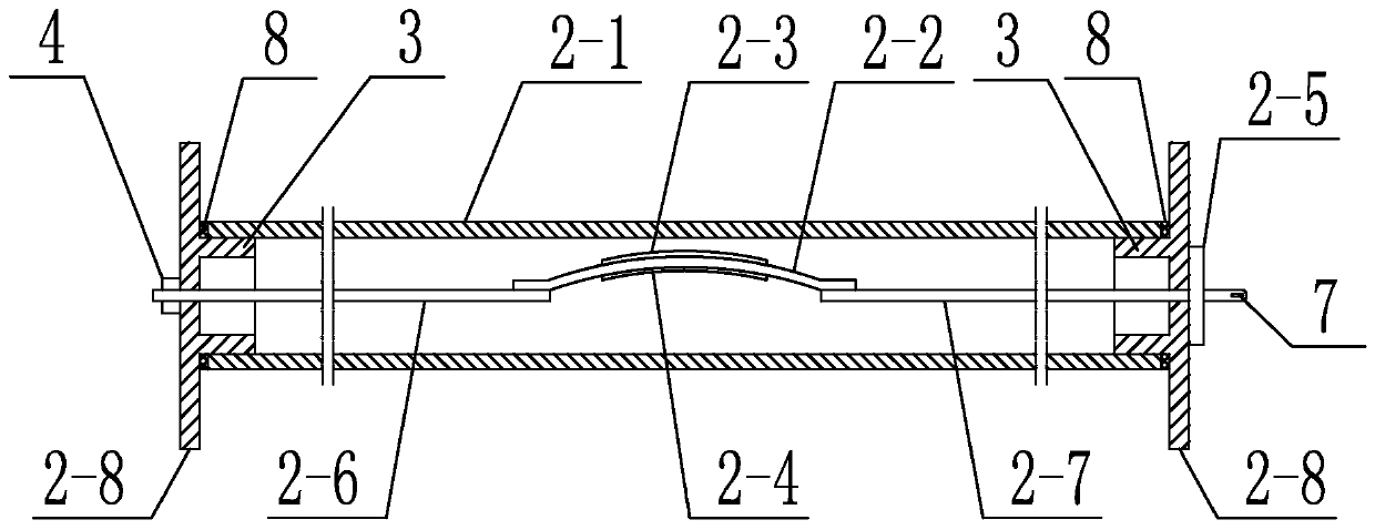
[0036] Specific implementation mode one: combine figure 1 , figure 2 , image 3 , Figure 4 , Figure 5 with Image 6 This embodiment is described. This embodiment includes a connection frame 1 and a plurality of test units 2, and a plurality of test units 2 are sequentially arranged on the connection frame 1 from bottom to top, and each test unit 2 includes a casing 2-1, Arched plate 2-2, upper strain gauge 2-3, lower strain gauge 2-4, moving outer cover 2-5, first thin rod 2-6, second thin rod 2-7 and two end caps 2- 8. The two ends of the casing 2-1 are detachably connected with two end caps 2-8, the arched plate 2-2 is set inside the casing 2-1, the upper strain gauge 2-3 and the lower strain gauge 2 -4 are respectively arranged on the top surface and the bottom surface of the arched plate 2-2, the two ends of the arched plate 2-2 are respectively provided with the first thin rod 2-6 and the second thin rod 2-7, the first thin rod One end of 2-6 is fixedly connected...

specific Embodiment approach 2

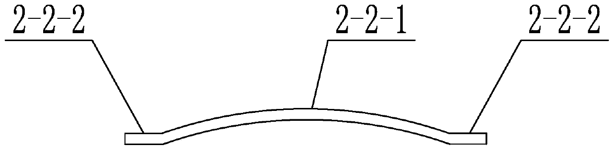
[0041] Specific Embodiment 2: This embodiment is a further limitation of Specific Embodiment 1. The arched plate 2-2 includes a curved plate 2-2-1 and two flat plates 2-2-2, and the curved plate 2-2-1 A flat plate 2-2-2 is respectively arranged at both ends of the arc plate 2-2-1 and two flat plates 2-2-2 are integrally made.

specific Embodiment approach 3

[0042] Specific embodiment 3: This embodiment is a further limitation of specific embodiment 1 or 2. The arched plate 2-2 is an elastic plate, and the arched plate 2-2 is arranged on the sleeve 2-1 along the length direction of the sleeve 2-1. within 1.


PUM


Abstract

The invention discloses a device and method for detecting deformation stress of an on-site cement-based material. Due to the fact that detection of shrinkage or expansion stress generated by concretedeformation is high in precision requirement, large in difficulty, low in efficiency and poor in accuracy, a test device and method for rapidly evaluating the shrinkage or expansion stress of concreteon a construction site are deficient. The two ends of a sleeve are detachably connected with the two end covers; an arched plate is arranged in the sleeve; an upper strain gauge and a lower strain gauge are arranged on the top surface and the bottom surface of the arched plate respectively; a first slender rod and a second slender rod are arranged at two ends of the arched plate respectively; oneend of the first slender rod is fixedly connected with the arched plate, and the other end of the first slender rod penetrates through the end cover close to the first slender rod; one end of the second slender rod is fixedly connected with the arched plate, and the other end of the second slender rod penetrates through the end cover close to the second slender rod and then is detachably connected with a movable outer cover; and a hanging opening is machined in the end, matched with the movable outer cover, of the second slender rod. The detection method is realized on the basis of the detection device. The method is used for detecting the shrinkage or expansion stress of the cement-based material.

Description

technical field [0001] The invention belongs to the technical field of civil engineering, and in particular relates to a detection device and a detection method for deformation stress of cement-based materials on site. Background technique [0002] The volume deformation of concrete is one of the important factors affecting the long-term strength and durability of cement-based materials. The volume deformation of cement-based materials under normal temperature or high temperature environment includes chemical shrinkage, plastic shrinkage, temperature shrinkage, drying shrinkage and carbonization shrinkage, etc. The deformation of cement-based materials at negative temperatures is more complicated. In addition to chemical shrinkage, plastic shrinkage, drying shrinkage, and carbonation shrinkage, the temperature deformation may be manifested as frost heave due to free water freezing. When the frost heave stress is greater than the early tensile strength of concrete When the s...

Claims


Application Information

Patent Timeline
IPC IPC(8): G01N33/38G01L5/00
CPCG01L5/00G01N33/383
Inventor 杨英姿陈智韬鞠成张歌刘琪
Owner HARBIN INST OF TECH
Why Eureka
Try Eureka