
Eureka
For R&D, Eureka makes reading and utilizing patents & technical documents easy.
Eureka AIR
Designed for self-driven R&D workflows. Generate viable solutions, solve complex R&D challenges, empower your innovation with AI.

Eureka Materials
Designed for material experts only. Revolutionize your material R&D, from search, analyze, to developing new materials.

TechResearch
Generate reliable direction feasibility study reports for your R&D in just a few steps.

TechSeek
Discover and master advanced knowledge NOW. Basics, ideas, possibilities, all at once.

TechMind
As an expert in R&D Theories, TechMind can generates customized viable solutions instantly.

TechRisk
Analyze your overall solution with one click, know your potential R&D risks in advance.

TechMonitor
Get weekly tech updates, stay abreast of the latest tech innovations and key insights.
Cooling device for at least one component mounted on printed circuit board and printed circuit board
A technology for printed circuit boards and cooling devices, which is applied in the directions of printed circuit components, printed circuits, printed circuits, etc., can solve problems such as increasing the installation workload.
- Summary
- Abstract
- Description
- Claims
- Application Information
AI Technical Summary
Problems solved by technology
Method used
Image

Examples
Embodiment Construction
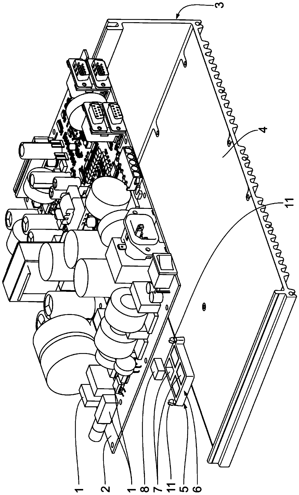
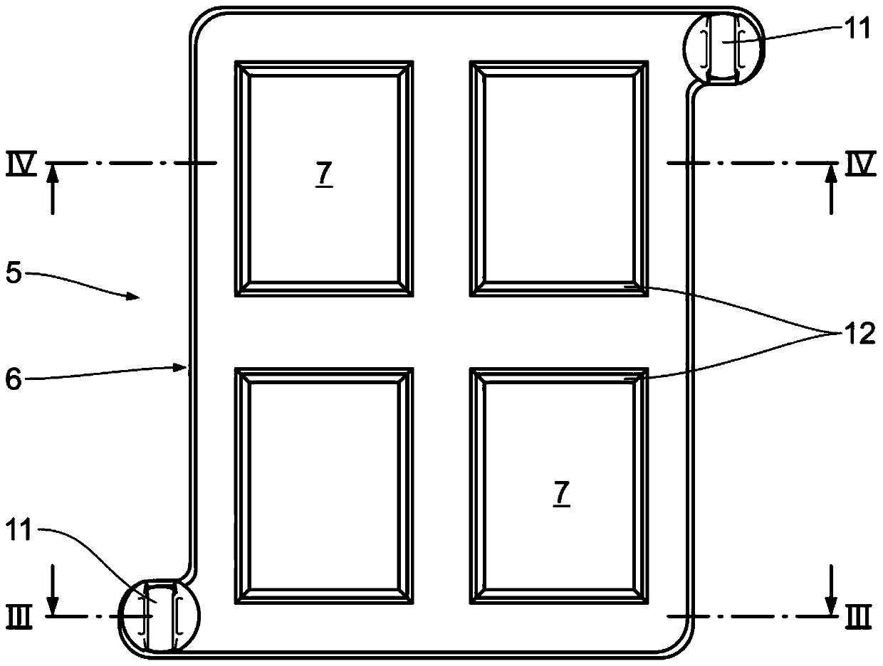
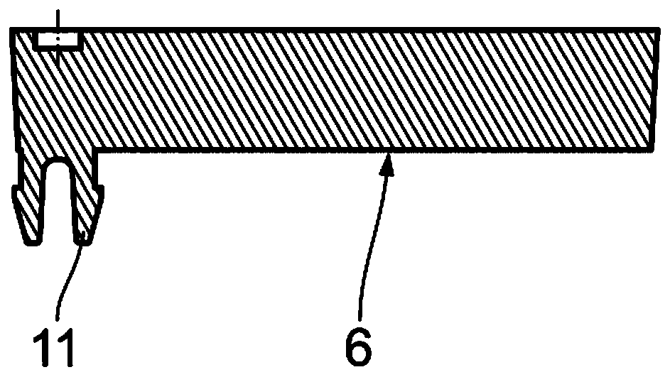
[0029] figure 1 A printed circuit board 2 equipped with various SMD components 1 and a metal housing 3 for receiving the printed circuit board 2 are shown in an exploded view. exist figure 1 , the components of the cooling device collectively designated 5 are arranged between the printed circuit board 2 and the bottom housing wall 4 of the metal housing 3 . The cooling device 5 serves to cool at least one of the components 1 mounted on the printed circuit board 2 . The cooling device 5 , as a heat conducting element frame, has a plastic heat sink frame 6 which includes four heat sink receptacles 7 as heat conducting element receptacles. The plastic material of the heat sink frame 6 is fireproof, electrically insulating, heat-resistant and shape-fixed.
[0030] The heat sink receptacle 7 is arranged complementary to the cuboid metal heat sink 8, one of which is in the figure 1 shown in . The metal cooling body 8 serves as a heat conducting element. The metal heat sink 8 c...
PUM
 Abstract
Description
Claims
Application Information
 - R&D Engineer
- R&D Manager
- IP Professional
- Industry Leading Data Capabilities
- Powerful AI technology
- Patent DNA Extraction
Browse by: Latest US Patents, China's latest patents, Technical Efficacy Thesaurus, Application Domain, Technology Topic, Popular Technical Reports.
© 2024 PatSnap. All rights reserved.Legal|Privacy policy|Modern Slavery Act Transparency Statement|Sitemap|About US| Contact US: help@patsnap.com