Packaging bag printing device

A printing device and packaging bag technology, applied in printing, printing machines, rotary printing machines, etc., can solve the problems of not meeting people's needs and reducing the printing effect of packaging bags, achieve good blocking effect, ensure stability, and improve printing efficiency effect

Inactive Publication Date: 2020-03-20
株洲蓝海包装有限公司
View PDF21 Cites 7 Cited by
  • Summary
  • Abstract
  • Description
  • Claims
  • Application Information

AI Technical Summary

Problems solved by technology

A packaging bag printing device in the above-mentioned patent has the following disadvantages: before printing the packaging bag, the dust removal work is not performed on the packaging bag, so that the printing effect of the device on the packaging bag is reduced, which cannot meet people's use needs

Method used


Image

  • Packaging bag printing device
  • Packaging bag printing device
  • Packaging bag printing device

Examples


Embodiment 1

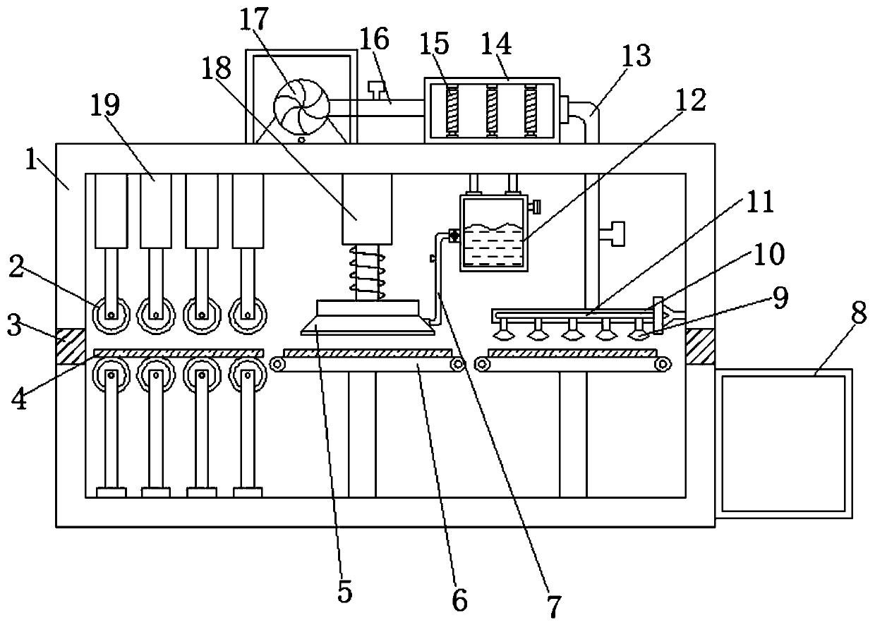
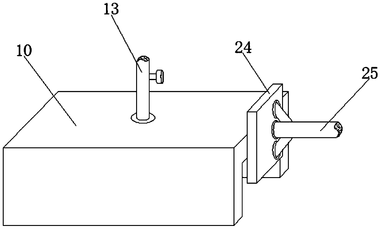
[0030] refer to Figure 1-3 , a packaging bag printing device, including a box body 1, the bottom inner wall of the box body 1 is connected with a second electric push rod 19 through bolts, and the outer wall of one side of the second electric push rod 19 is rotatably connected with a transmission roller 2, and the box body The bottom inner wall of 1 is connected with a support rod through bolts, and the outer wall of one side of the support rod is rotatably connected with a driven roller, the top outer wall of the driven roller is placed with the packaging bag body 4, and the outer walls of both sides of the box body 1 are opened. Groove 3, the top inner wall of the box body 1 is connected with the first electric push rod 18 by bolts, and the outer wall of one end of the first electric push rod 18 is connected with the printing head 5 by bolts, and the outer wall of one end of the first electric push rod 18 is sleeved with The spring, the top inner wall of the box body 1 is c...

Embodiment 2

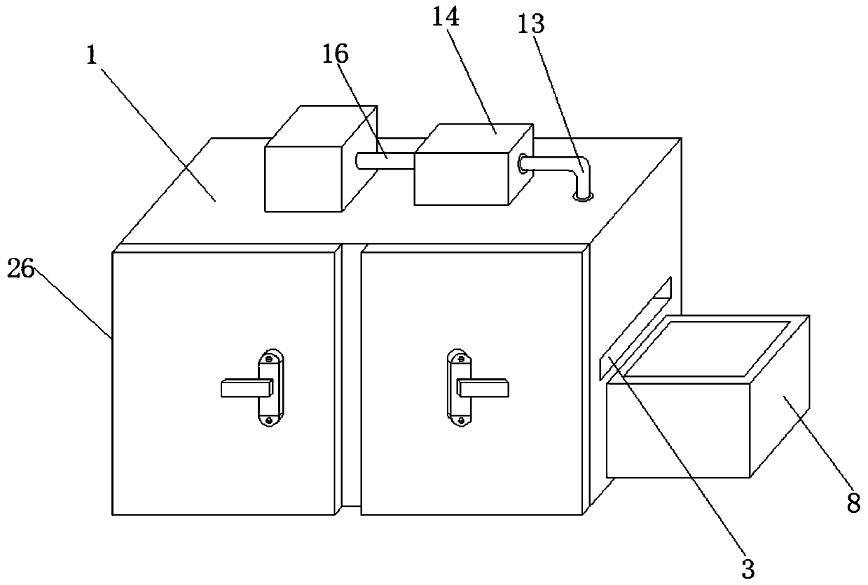
[0034] refer to Figure 4 , a packaging bag printing device. Compared with Embodiment 1, the top outer wall of the box body 1 is connected with an air pump 20 by bolts, and an air suction pipe 21 is plugged into one side of the air pump 20. The air suction pipe 21 One end of the dust box 22 is plugged in, and the inner walls on both sides of the dust box 22 are connected with dust filter bags 23 by bolts.

[0035] Working principle: When in use, the air pump 20 can be activated before the device prints the packaging bag, which can effectively suck the dust on the surface of the packaging bag body 4 into the dust collection box 22, thereby improving the pressure of the subsequent printing head 5 on the packaging bag body 4. Printing effect, then when the staff inserts the packaging bag body 4 from the through slot 3, the second electric push rod 19 can be activated, and the second electric push rod 19 drives the transmission roller 2 to move down to clamp and fix the packaging ba...


PUM


Abstract

The invention discloses a packaging bag printing device. The device comprises a box body; a second electric push rod is arranged on the inner wall of the bottom of the box body; the outer wall of oneside of the second electric push rod is rotationally connected with a transmission roller; a supporting rod is arranged on the inner wall of the bottom of the box body; a driven roller is rotatably connected to the outer wall of one side of the supporting rod; a packaging bag body is placed on the outer wall of the top of the driven roller; through grooves are formed in the outer walls of the twosides of the box body respectively; a first electric push rod is arranged on the inner wall of the top of the box body; and a printing head is arranged on the outer wall of one end of the first electric push rod. After the packaging bag body is printed, an air blower and a resistance wire can be started, cold air generated by the air blower is blown out of an air outlet hopper after being heated by the resistance wire, the packaging bag body can be effectively dried, the printing efficiency is improved, a good blocking effect can be achieved when the packaging bag body is dried by a protectionshell, and the stability of the packaging bag body is guaranteed.

Description

technical field [0001] The invention relates to the technical field of packaging bag printing, in particular to a packaging bag printing device. Background technique [0002] Printing is a technology that transfers the ink to the surface of paper, fabric, plastic, leather and other materials through plate making, ink application, and pressurization to copy the contents of the original manuscript in batches. [0003] After searching, the Chinese patent publication number is CN207128392U, which discloses a packaging bag printing device, which includes a conveying roller at the front end of the frame, a nip roller on the rear side of the conveying roller, a printing table on the rear side of the nip roller, and a printing table on the upper part of the printing table. Set up a printing machine, the printing machine is slidingly connected with the slide rail, the slide rail is fixed on the frame, a traction roller is arranged on the rear side of the printing machine, a first dry...

Claims


Application Information

Patent Timeline
Patent Type & Authority Applications(China)
IPC IPC(8): B41F17/00B41F23/00B41F23/04
CPCB41F17/00B41F23/002B41F23/0443B41F23/0466
Inventor 李晓娟林凤龙张艳华
Owner 株洲蓝海包装有限公司
Why Eureka
Try Eureka