
Shaft gravity type stock bin

A gravity-type, silo technology, applied in the field of automated production equipment, can solve problems such as high labor costs, difficult manufacturing, and high prices, and achieve the effects of being easy to grab by manipulators, improving efficiency, and ensuring smoothness

Pending Publication Date: 2020-03-20
思乐福智能科技(苏州)有限公司
View PDF0 Cites 6 Cited by
  • Summary
  • Abstract
  • Description
  • Claims
  • Application Information

AI Technical Summary

Problems solved by technology

In the field of existing machinery manufacturing, the handling of materials and the loading and unloading of workpieces are relatively weak links. The existing feeding mechanism cannot meet the actual production requirements due to its complex structure, difficult manufacturing and high price, and requires a lot of manpower and material resources. With the cooperation, it not only has high labor cost, but also has certain dangers, and also greatly reduces the level of production automation.
[0003] Especially for the loading of the shaft bar structure, since this type of material is a cylindrical structure with a certain length, it will roll and cannot be positioned, and there will be a disorderly arrangement of horizontal and vertical crossings, which makes it impossible to realize automatic For loading operation, in actual use, a hopper will be set at the position of the loading mechanism for stacking bars. However, it is only a bracket, which cannot realize automatic loading, and cannot adjust the size to meet the needs of bars of different lengths.

Method used


Image

  • Shaft gravity type stock bin
  • Shaft gravity type stock bin
  • Shaft gravity type stock bin

Examples


Embodiment Construction

[0029] Embodiments of the technical solutions of the present invention will be described in detail below in conjunction with the accompanying drawings. The following examples are only used to illustrate the technical solutions of the present invention more clearly, and therefore are only examples, rather than limiting the protection scope of the present invention.

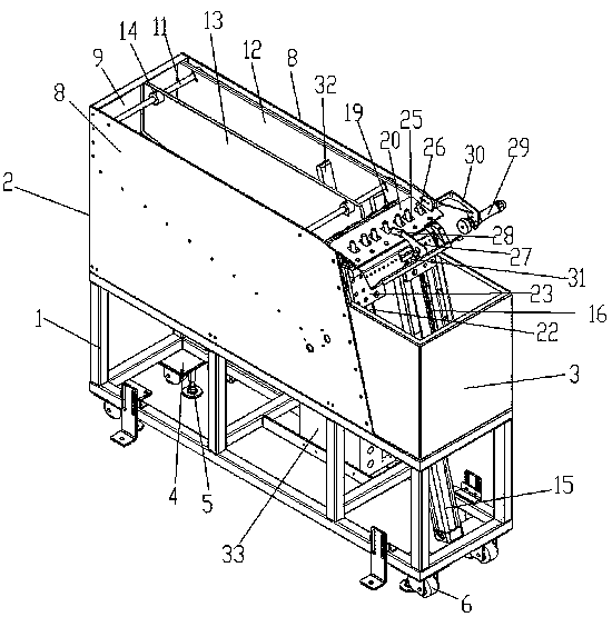
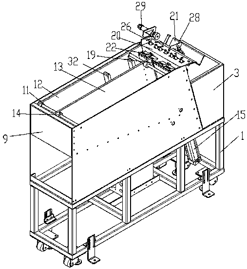
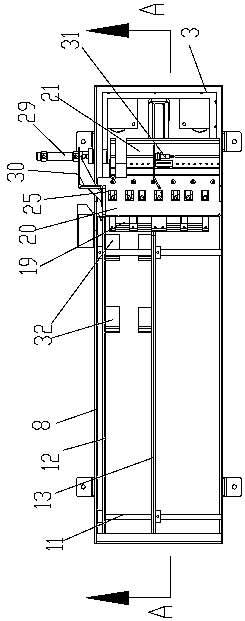
[0030] Such as Figure 1~5 As shown, the present invention discloses a shaft-type gravity feed bin, which is mainly aimed at feeding various metals, plastics, nylon and other cylindrical bars. Its structure includes a support frame 1, which is installed on the The upper storage bin 2 is installed on the support frame 1 and is located at the U-shaped protective plate 3 at the front end of the storage bin, and the jacking and feeding mechanism installed on the front end of the storage bin. inside the shield.

[0031] Specifically, the support frame 1 is a frame structure composed of a plurality of aluminum alloy pr...


PUM

PropertyMeasurementUnit
Slopeaaaaaaaaaa

Abstract

The invention discloses a shaft gravity type stock bin. The stock bin comprises a supporting frame, a storage bin installed on the supporting frame and a jacking feeding mechanism installed in the front end face of the storage bin, a fixed side plate and an adjusting side plate are arranged in the storage bin in parallel, and the position of the adjusting side plate is adjustable, so that a widthadjustable feeding bin is formed between the adjusting side plate and the fixed side plate; the feeding mechanism comprises a jacking air cylinder, a telescopic rod of the jacking air cylinder is connected with a sliding block, an adjusting plate is connected with the sliding block through a connecting block, a feeding base is installed at the upper end of the adjusting plate, a discharging platform plate is obliquely installed at the top of the front end face of the storage bin, a V-shaped material frame is installed at the front end of the discharging platform plate, and the jacking air cylinder is cooperated with the feeding base, the oblique bottom face and the feeding platform plate. Thus, a bar material rolls into the V-shaped material frame through the dead weight of the bar material itself, and automatic feeding of the bar material is realized effectively.

Description

technical field [0001] The invention relates to an automatic production equipment, in particular to a shaft type gravity feed bin with automatic feeding function. Background technique [0002] With the development of economy and construction, and the popularization of mechanization, the construction scale and production scale of all walks of life are rapidly expanding, and the requirements for automatic feeding mechanisms are getting higher and higher. In the field of existing machinery manufacturing, the handling of materials and the loading and unloading of workpieces are relatively weak links. The existing feeding mechanism cannot meet the actual production requirements due to its complex structure, difficult manufacturing and high price, and requires a lot of manpower and material resources. With the cooperation, it not only has high labor cost, but also has certain dangers, and also greatly reduces the level of production automation. [0003] Especially for the loading...

Claims


Application Information

Patent Timeline
IPC IPC(8): B65G65/38B65G69/00B65G47/82
CPCB65G47/82B65G65/38B65G69/00B65G2201/0217
Inventor 江中华柯尊锋汪文昌
Owner 思乐福智能科技(苏州)有限公司
Learn More