Eureka AIR delivers breakthrough ideas for toughest innovation challenges, trusted by R&D personnel around the world.

Optical fiber ribbon residual torsion testing device and testing method thereof

A test device and residual torsion technology, applied in the direction of measuring devices, instruments, scientific instruments, etc., can solve the problems of affecting the torsion angle of the optical fiber ribbon, large reading errors, and affecting test results, etc., to improve test accuracy and reduce readings Effect of error, exact determination

Pending Publication Date: 2020-03-20
CHENGDU TAIRUI COMM EQUIP DETECTION
View PDF0 Cites 1 Cited by
  • Summary
  • Abstract
  • Description
  • Claims
  • Application Information

AI Technical Summary

Problems solved by technology

[0009] a. It is difficult to adjust the balance when the pointer is clamped on the lower end of the optical fiber ribbon, thus exerting an external force on the optical fiber ribbon and affecting the torsion angle of the optical fiber ribbon; and it is easy to appear that the front and rear are not concentric, thus affecting the accuracy of the test results
[0010] b. The self-weight of the pointer is unavoidable, causing the test conditions to fail to meet the standard requirements
[0011] c. According to the pointer pointing, the reading will be limited by objective factors such as dust cover, fixing clip, upper cross arm, etc., making it difficult to read from the direction perpendicular to the dial, resulting in large reading errors and affecting the accuracy of test results
[0012] d. The torsion angle needs to be calculated twice according to the pointer reading, so the error will be introduced twice, which will affect the final test result

Method used


Image

  • Optical fiber ribbon residual torsion testing device and testing method thereof
  • Optical fiber ribbon residual torsion testing device and testing method thereof
  • Optical fiber ribbon residual torsion testing device and testing method thereof

Examples


Embodiment Construction

[0033] The present invention will be further described below in conjunction with the accompanying drawings.

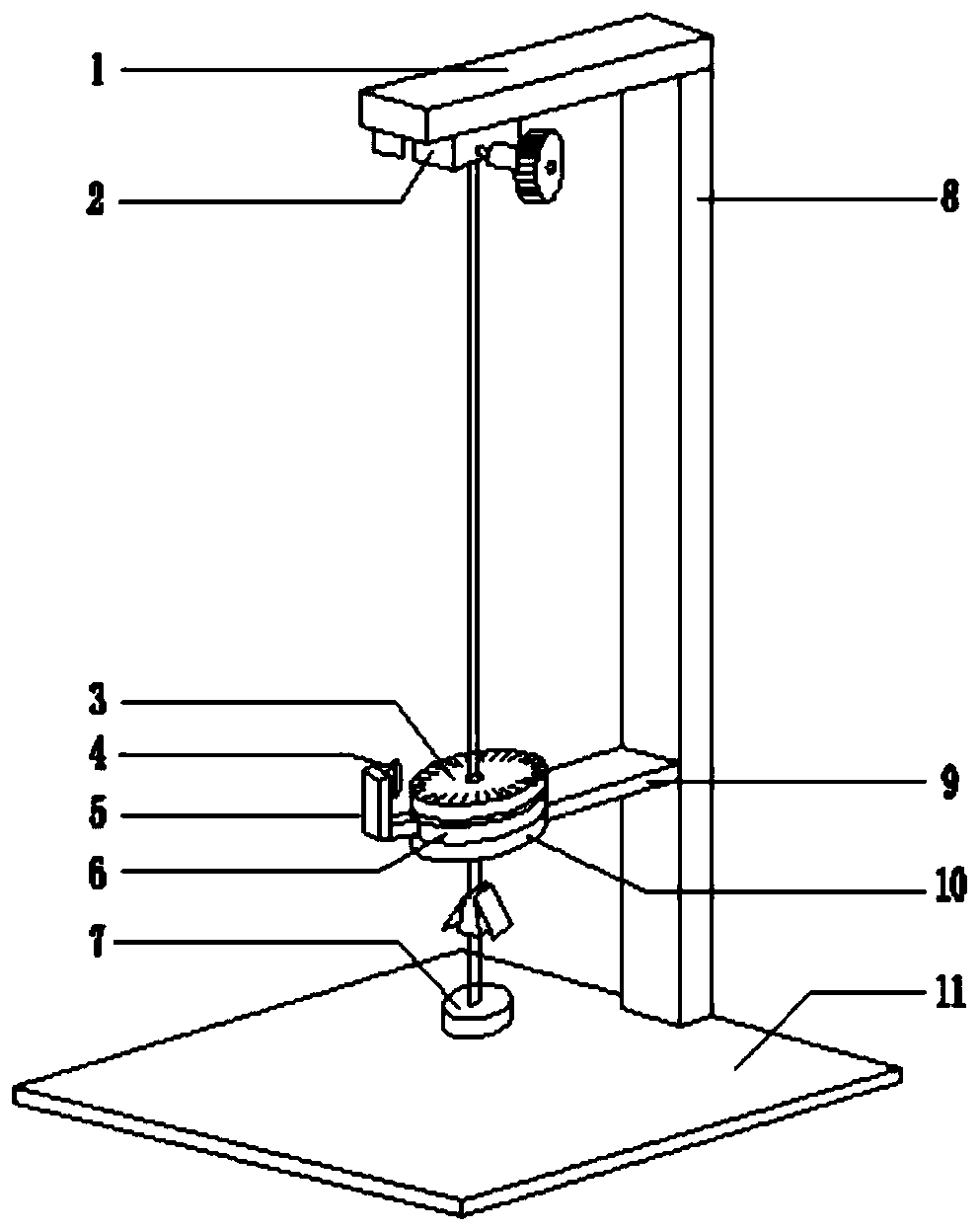
[0034] Such as figure 1 As shown, a fiber optic ribbon residual torsion test device includes: a support structure, a light source turntable 6, a dial 3, and a tray 10. The top of the support structure has an optical fiber ribbon fixing clip 2 for clamping the optical fiber ribbon to be tested. Between the top of the support structure and the base 11 of the support structure, a tray 10 fixed to the support structure on a horizontal plane is arranged; The disk 3 and the tray 10 have through holes in the same center, and the through holes are used to vertically pass through the optical fiber ribbon to be tested. The light source turntable 6 and the dial 3 can rotate horizontally independently of each other. The light source 4 is rotated by the light source turntable 6 , and the light source 4 irradiates the shadow of the optical fiber under test on the scale plate 3 .

...


PUM


Abstract

The invention relates to the technical field of residual torsion testing, and discloses an optical fiber ribbon residual torsion testing device. An optical fiber ribbon fixing clamp is arranged at thetop end of a supporting structure and used for clamping a measured optical fiber ribbon, and a tray which is fixed to the supporting structure and located on the horizontal plane is arranged betweenthe top end of the supporting structure and a base of the supporting structure; the light source turntable and the dial are sequentially arranged on the tray; wherein the light source turntable, the dial and the tray are provided with through holes with the same center, the through holes are used for vertically passing through a measured optical fiber ribbon, the light source turntable and the dial can mutually independently and horizontally rotate, a light source rotating along with the light source turntable is arranged on the light source turntable, and shadows of measured optical fibers irradiated by the light source are on the dial. According to the scheme, the reading error is effectively reduced, and the influence of external force on the optical fiber ribbon is avoided, so that thenatural state of the optical fiber ribbon is kept, and the angle reading accuracy is improved. Meanwhile, the invention further discloses a testing method of the optical fiber ribbon residual torsiontesting device.

Description

technical field [0001] The invention relates to the technical field of residual torsion testing, in particular to an optical fiber ribbon residual torsion testing device and a testing method thereof. Background technique [0002] Optical communication technology has the advantages of large capacity and low loss, and is an important foundation of modern communication. [0003] In recent years, my country's optical communication industry has developed rapidly, and the application range of optical fibers and optical cables is also increasing. [0004] The optical fiber structure in the optical cable is mainly divided into: optical fiber ribbon and discrete optical fiber. [0005] The optical fiber ribbon is a thin flat ribbon formed by a plurality of (2-24) optical fibers arranged in parallel and solidified. The optical fiber cable with the optical fiber ribbon structure in the cable is called an optical fiber ribbon cable. The optical fiber ribbon cable is often used in local...

Claims


Application Information

Patent Timeline
Patent Type & Authority Applications(China)
IPC IPC(8): G01N3/26G01N3/06
CPCG01N3/26G01N3/062G01N2203/0021G01N2203/028G01N2203/0605
Inventor 孔超薛梦驰时彬杨先金李吉超
Owner CHENGDU TAIRUI COMM EQUIP DETECTION
Why Eureka
Eureka Blog
Learn More