Liquidometer on-site detecting system and method for high-voltage direct-current converter valve cooling system

A high-voltage direct current and cooling system technology, applied in liquid/fluid solid measurement, measurement devices, test/calibration devices, etc., can solve the problems of high requirements for liquid level gauge transportation, large errors in manual readings, and affecting detection efficiency, etc. , to achieve the effect of improving test efficiency, reducing reading error and wide adaptability

Pending Publication Date: 2018-03-02
EXAMING & EXPERIMENTAL CENT OF ULTRAHIGH VOLTAGE POWER TRANSMISSION COMPANY CHINA SOUTHEN POWER GRID
View PDF6 Cites 2 Cited by
  • Summary
  • Abstract
  • Description
  • Claims
  • Application Information

AI Technical Summary

Problems solved by technology

The traditional method has several defects: (1) The traditional detection method has a huge device and can only be used for laboratory testing. It is inefficient for the inspection of the liquid level gauge and has high requirements for the transportation of the liquid level gauge.
(2) In the traditional detection method, because the liquid level gauge is vertically inserted into the verification water tank, the detection of the liquid level gauge needs to customize the fixing fixtures for different types of liquid level gauges. This process takes a long time and seriously affects the detection efficiency.
(3) The installation and measurement (including the water level control of each measurement point) of the traditional detection method are manual. The standard device for measurement is usually a ruler, and the manual reading error is too large
(4) The traditional detection method needs to consume nearly one hundred liters of pure water for each detection, which is poor in economy

Method used


Image

  • Liquidometer on-site detecting system and method for high-voltage direct-current converter valve cooling system
  • Liquidometer on-site detecting system and method for high-voltage direct-current converter valve cooling system
  • Liquidometer on-site detecting system and method for high-voltage direct-current converter valve cooling system

Examples


Embodiment 1

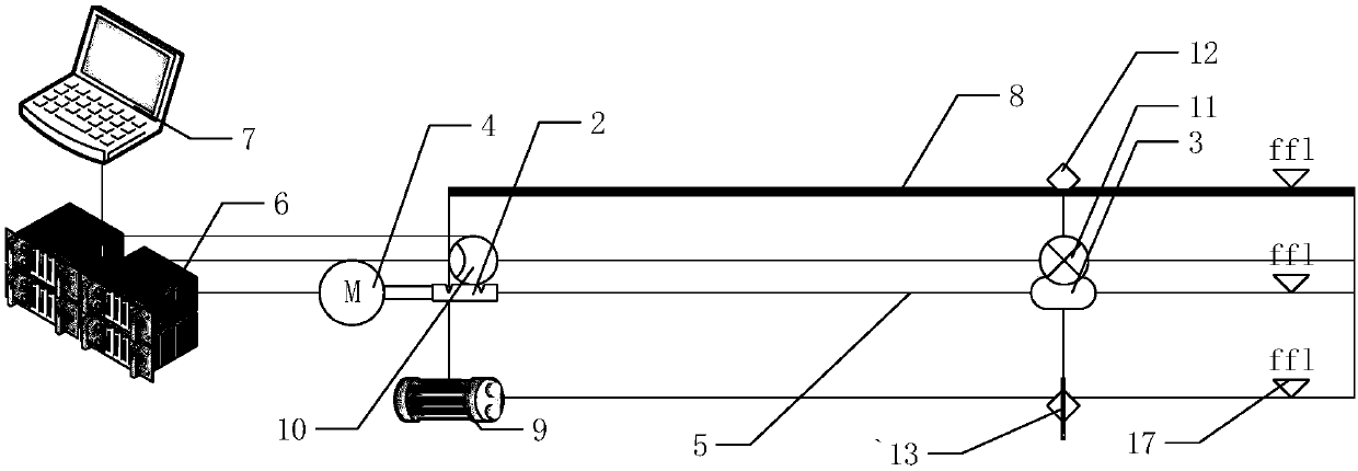
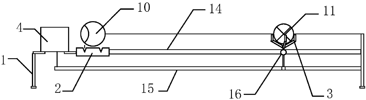
[0053] Such as figure 1 , figure 2 As shown, an on-site detection system for a liquid level gauge of a high-voltage DC converter valve cooling system includes a platform support 1, a transmitter base 2, a float base 3, a stepping motor 4, a linear displacement mechanism 5, and a control module 6. Computer module 7, steel ruler 8, laser rangefinder 9; the transmitter base 2 is used to clamp and fix the transmitter head 10 of the liquid level gauge, and the floating ball base 3 is used To clamp and fix the float 11 of the liquid level gauge, the transmitter base 2 and the float base 3 are respectively arranged on the linear displacement mechanism 5, and the stepping motor 4 drives the linear displacement mechanism 5 to make the float The base 3 moves back and forth linearly relative to the transmitter base 2. The measuring direction of the steel ruler 8, the ray direction of the laser rangefinder 9 and the moving direction of the linear displacement mechanism 5 are parallel to...

Embodiment 2

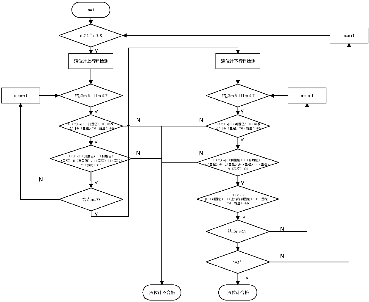
[0055] A method for on-site detection of a liquid level gauge in a cooling system of a HVDC converter valve, the specific steps are as follows:

[0056] Step 1. Install and fix the liquid level gauge, and adjust the level;

[0057] Step 2. If the liquid level meter is set point adjustable, proceed to step 10, if not, set the number of detection points, including the upper limit point, lower limit point and detection point, not less than 5 points;

[0058] Step 3. The equipment is initialized, the equipment drives the liquid level gauge to determine the full scale and zero position, and moves to the positions of each detection point at the same time;

[0059] Step 4. Preheat the liquid level gauge with power supply;

[0060] Step 5. Measure the indication value of each detection point. When detecting, use the method of "aligning with the standard to be inspected". The liquid level gauge under inspection starts from the zero position and gradually moves up to each detection poi...


PUM


Abstract

The invention relates to a liquidometer on-site detecting system and method for a high-voltage direct-current converter valve cooling system. The liquidometer on-site detecting system comprises a platform support, a transmitter base, a floating ball base, a stepping motor, a linear displacement mechanism, a control module, a computer module, a straight steel ruler and a laser range finder; the control module is used for controlling the stepping motor and receiving electric signals of the transmitter on the transmitter base and the laser range finder; the computer module is used for processingoutput signals of the control module; the transmitter base, the floating base, the stepping motor and the linear displacement mechanism are arranged on the platform support. The liquidometer on-site detecting system has the advantages that the control module is used for controlling the stepping motor and receiving electric signals of the transmitter on the transmitter base and the laser range finder, the computer module is used for processing output signals of the control module, and the transmitter base, the floating base, the stepping motor and the linear displacement mechanism are arrangedon the platform support.

Description

technical field [0001] The invention relates to the technical field of liquid level gauge measurement, in particular to an on-site liquid level gauge detection system and method for a high-voltage direct current converter valve cooling system. Background technique [0002] The expansion of the application of liquid level gauges and the renewal of technology have put forward higher and higher requirements for the verification efficiency, accuracy and automation of the verification device. At present, the valve cooling system of each DC converter station is equipped with various types of liquid level gauges to measure the liquid level of the valve cooling system expansion tank, spray pool, etc., and the measurement signal is sent to the valve cooling protection system and control system. Water replenishment control module. At present, the domestic liquid level gauge verification technology generally adopts the principle of the connector, which is bulky and can only be verifie...

Claims


Application Information

Patent Timeline
Patent Type & Authority Applications(China)
IPC IPC(8): G01F25/00
CPCG01F25/20
Inventor 彭德辉
Owner EXAMING & EXPERIMENTAL CENT OF ULTRAHIGH VOLTAGE POWER TRANSMISSION COMPANY CHINA SOUTHEN POWER GRID
Why Eureka
Try Eureka