Machine part production paint spraying device

A technology of mechanical parts and the other side, applied in the field of paint spraying device production of mechanical parts, can solve the problem of inability to dry the board, and achieve the effect of improving stability, improving uniformity and adequacy, and ensuring completeness

Inactive Publication Date: 2020-03-24
ZHUZHOU HUAXIN PRECISION IND
View PDF6 Cites 6 Cited by
  • Summary
  • Abstract
  • Description
  • Claims
  • Application Information

AI Technical Summary

Problems solved by technology

[0004] Based on the technical problem that the existing paint spraying device cannot dry the plate after painting in time, the present invention proposes a paint spraying device for the production of mechanical parts

Method used


Image

  • Machine part production paint spraying device
  • Machine part production paint spraying device
  • Machine part production paint spraying device

Examples


Embodiment 1

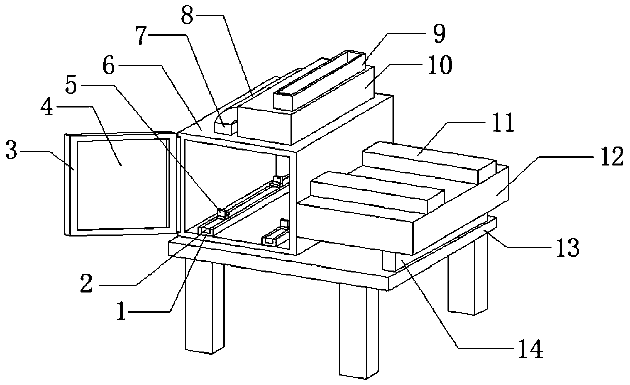
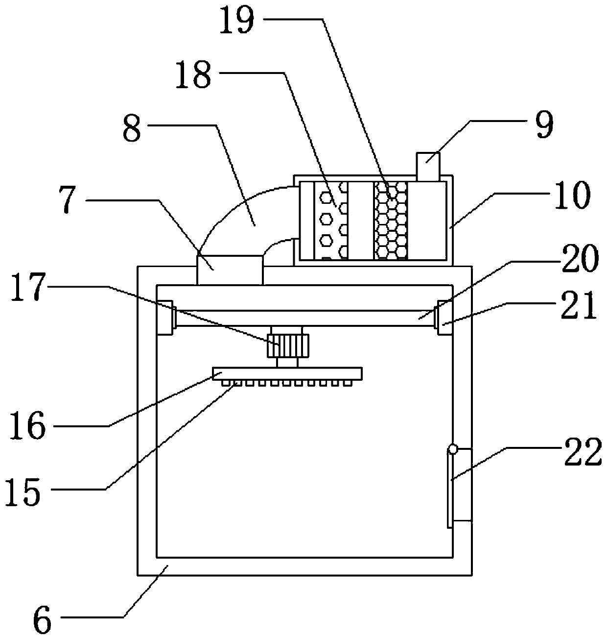
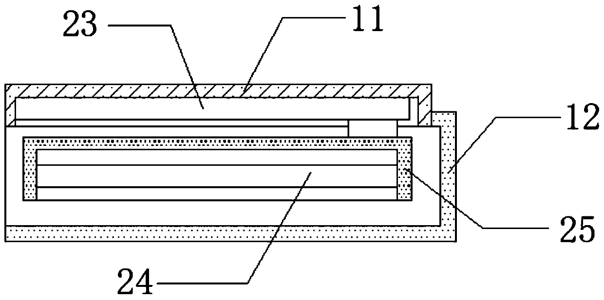
[0029] refer to Figure 1-3 , a painting device for the production of mechanical parts, comprising a support base 13 and four support legs, the four support legs are respectively installed on the bottom four-corner outer walls of the support base 13 by bolts, and the top side outer wall of the support base 13 is connected with a paint spraying box by bolts body 6, and the bottom outer wall on one side of the paint spraying box body 6 is connected with a third supporting shell 12 arranged horizontally by bolts, and the outer walls at both ends of the top of the third supporting shell 12 are connected with a second supporting shell 11 by bolts. The top inner wall of each second supporting shell 11 is connected with the third electric guide rail 23 by bolts, the bottom outer walls of the two third electric guide rails 23 are all slidably connected with the third electric slider, the bottom of the two third electric slider The same fourth support shell 25 is connected by bolts, th...

Embodiment 2

[0034] refer to Figure 1-4 , a paint spraying device for producing mechanical parts, also includes a support screen 26 installed at the same level on the bottom inner wall of the paint spray box body 6 both sides by bolts, and two support groove plates 1 are installed on the support screen 26 by bolts The same slag storage tank plate 27 is plugged between the outer walls on both sides of the top, the inner wall at the bottom of the painting box body 6 and the outer wall at the bottom of the support net plate 26 .

[0035] In the process of use, the paint slag produced by the painting process is collected by the slag storage tank plate 27. After the painting is completed, the slag storage tank plate 27 is pulled out to facilitate the unified cleaning of the paint slag and avoid long-term accumulation of paint slag in the spray paint. The bottom of the box affects the use of the device.


PUM


Abstract

The invention belongs to the technical field of machine part production, and specially relates to a machine part production paint spraying device. Aim at solving the problem that an existing paint spraying device cannot dry painted plates in time, the scheme is proposed that the paint spraying device comprises a supporting base and four supporting legs; the four supporting legs are installed on the outer walls of the four corners of the bottom of the supporting base through bolts respectively; a paint spraying box body is fixedly installed on the outer wall of one side of the top of the supporting base, and a horizontally-arranged third supporting shell is fixedly installed on the outer wall of the bottom of one side of the paint spraying box body. In the present invention, the machine part production paint spraying device is provided. A fourth electric guide rail, fourth electric sliding blocks and clamping blocks are arranged; a mechanical plate needing to be subjected to paint spraying treatment can be placed among the four clamping blocks, the four clamping blocks are driven by the four fourth electric sliding blocks to move, the mechanical plate is effectively clamped by the four clamping blocks, the stability of the mechanical plate is improved, and then the stability of paint spraying is improved.

Description

technical field [0001] The invention relates to the technical field of mechanical parts production, in particular to a painting device for the production of mechanical parts. Background technique [0002] Machinery accessories refer to various parts and accessories used for replacement and maintenance of construction machinery, production equipment, transportation equipment, etc. of enterprises. Such as crankshafts, pistons, bearings, etc. As we all know, the mechanical parts spraying device is an auxiliary device used to spray the surface of mechanical parts to improve the corrosion resistance, acid and alkali resistance, wear resistance and aesthetics of mechanical parts. It is used in the field of mechanical parts processing and spraying technology has been widely used. [0003] In the painting process of mechanical parts, a kind of painting equipment will be used. During the use of existing painting equipment, it is necessary to take out the painted mechanical parts pl...

Claims


Application Information

Patent Timeline
Patent Type & Authority Applications(China)
IPC IPC(8): B05B13/04B05B14/40B05B14/43B05B16/20
CPCB05B13/041B05B14/40B05B14/43B05B16/20
Inventor 刘星
Owner ZHUZHOU HUAXIN PRECISION IND
Why Eureka
Try Eureka