Improved pipe end beveling machine

A beveling machine and an improved technology, applied in the field of beveling machines, can solve the problems of inability to accurately process U-shape, insufficient processing stability, small configuration and engineering quantity, etc., to improve processing stability and increase the processing range of pipe diameter. , Good anti-loosening effect

Pending Publication Date: 2020-03-24
四川艾普耐斯油气工程服务有限公司
View PDF1 Cites 1 Cited by
  • Summary
  • Abstract
  • Description
  • Claims
  • Application Information

AI Technical Summary

Problems solved by technology

[0002] The beveling machine is a special tool for chamfering and beveling pipes or flat plates on the front end of welding. Simple, standard angle, smooth surface, etc., the invention patent with the announcement number CN201979162U is named as a fixed pipe numerical control end face beveling machine, which includes a rack guide rail and a main machine arranged on the rack guide rail, and the main machine A cutterhead is arranged on the top, and the cutterhead rotates around the main shaft of the main engine. The cutterhead is provided with a track fixedly installed along the radial direction of the cutterhead. The processing of different end face grooves can flexibly meet the processing of pipes of different lengths with a very small configuration and engineering quantity. However, in recent years, the construction of oil pipelines in my country has increased, and the demand for high-quality U-shaped and other complex grooves has increased. Now There are domestic pipe end beveling machines with small processing range, insufficient processing stability, and inability to accurately process complex bevels such as U-shaped

Method used


Image

  • Improved pipe end beveling machine
  • Improved pipe end beveling machine
  • Improved pipe end beveling machine

Examples


Embodiment

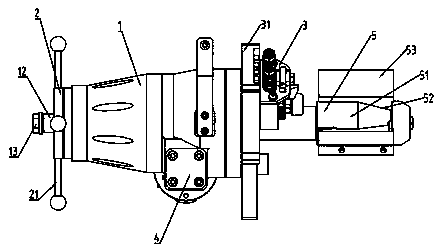
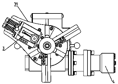
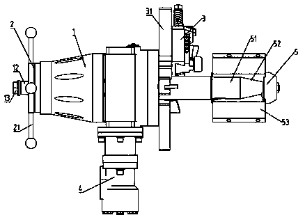
[0026] Example: According to Figure 1-4 It can be seen that an improved pipe end beveling machine includes a main shaft part 1, a feed part 2 is provided at one end of the main shaft part 1, a tie rod shaft 11 runs through the main shaft part 1, and a tie rod shaft 11 is sleeved on the main shaft part 1. Gripper shaft 12, a jaw nut 13 is installed at the tail end of the jaw shaft 12, a tapered roller bearing 14 is provided inside the main shaft part 1, and a processing cutterhead that can rotate relatively is provided at the other end of the main shaft part 1 Part 3, the hydraulic drive part 4 for driving the processing cutter head part 3 is provided under the main shaft part 1, and the other end of the pull rod shaft 11 is connected with a jaw part 5; The connecting sleeve 51 on the pull rod shaft 11, the connecting sleeve 51 is provided with an inclination angle 52, the connecting sleeve 51 is equipped with a jaw member 53, and the clamping jaw member 53 is threadedly conne...


PUM

PropertyMeasurementUnit
angleaaaaaaaaaa

Abstract

The invention discloses an improved pipe end beveling machine, which comprises a main shaft part. A feeding part is arranged at one end of the main shaft part; a pull rod shaft runs through the main shaft part; a clamping jaw shaft is sleeved on the pull rod shaft; a clamping jaw nut is mounted at the tail end of the clamping jaw shaft; a tapered roller bearing is arranged in the main shaft part;the other end of the main shaft part is provided with a processing cutter head part capable of rotating relatively; a hydraulic driving component used for driving the processing cutter head part is arranged under the main shaft part; and the other end of the pull rod shaft is connected with a clamping jaw component. The invention relates to the field of beveling machines; and through a novel mainshaft structure, the beveling machine is higher in stiffness by more than 1.5 times than a similar domestic beveling machine; the novel expansion claw structure increases the expansion force and solves the problem of indentation on the inner wall of the pipe; and equipped with a high-precision tracking cutter frame, the equipment can machine complex grooves such as U-shaped grooves and double-V-shaped grooves, and is convenient to use.

Description

technical field [0001] The invention relates to the technical field of beveling machines, in particular to an improved pipe end beveling machine. Background technique [0002] The beveling machine is a special tool for chamfering and beveling pipes or flat plates on the front end of welding. Simple, standard angle, smooth surface, etc., the invention patent with the announcement number CN201979162U is named as a fixed pipe numerical control end face beveling machine, which includes a rack guide rail and a main machine arranged on the rack guide rail, and the main machine A cutterhead is arranged on the top, and the cutterhead rotates around the main shaft of the main engine. The cutterhead is provided with a track fixedly installed along the radial direction of the cutterhead. The processing of different end face grooves can flexibly meet the processing of pipes of different lengths with a very small configuration and engineering quantity. However, in recent years, the constru...

Claims


Application Information

Patent Timeline
Patent Type & Authority Applications(China)
IPC IPC(8): B23D79/00B23Q3/06B23Q5/34
CPCB23D79/00B23Q3/064B23Q5/34
Inventor 余宏谭礼群
Owner 四川艾普耐斯油气工程服务有限公司
Why Eureka
Try Eureka