
Multi-energy complementary power supply system for offshore oil drilling platform and control method thereof

A technology for drilling platforms and offshore oil, applied in the field of energy management, can solve problems that affect the stable operation of the system, exit, and reduce system utilization

Active Publication Date: 2020-03-24
CHINA UNIV OF PETROLEUM (EAST CHINA)
View PDF5 Cites 2 Cited by
  • Summary
  • Abstract
  • Description
  • Claims
  • Application Information

AI Technical Summary

Problems solved by technology

[0006] However, due to space constraints on offshore drilling platforms, usually only a single energy storage device can be used to regulate
However, a single energy-type energy storage device cannot quickly respond to the dynamic power fluctuations of the system, resulting in power imbalance and affecting the stable operation of the system. Although a single power-type energy storage device can quickly respond to dynamic changes in system power, it is limited by its own capacity. When the system power increases, it is easy to make it in a lower state of charge, and then quit the working state. The load can only be in the running state of load shedding, which reduces the system utilization.

Method used


Image

  • Multi-energy complementary power supply system for offshore oil drilling platform and control method thereof
  • Multi-energy complementary power supply system for offshore oil drilling platform and control method thereof
  • Multi-energy complementary power supply system for offshore oil drilling platform and control method thereof

Examples


Embodiment Construction

[0049] The present invention will be further described below in conjunction with accompanying drawings and examples of implementation.

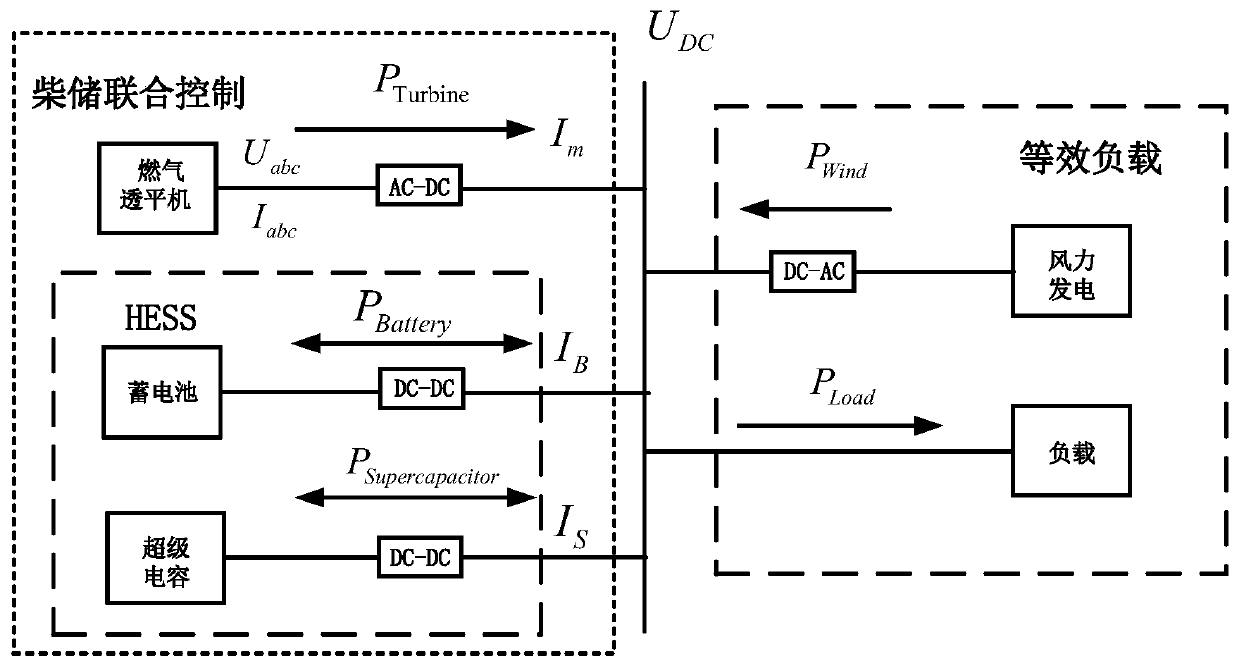
[0050] figure 1 It is the topological structure and signal acquisition diagram of the multi-energy complementary power supply system of the offshore drilling platform mentioned in the present invention. A multi-energy complementary power supply system for an offshore oil drilling platform described in the present invention mainly includes the following components: a gas turbine generator set, a battery pack, a supercapacitor pack, a wind power generator set, a load, and a DC-AC converter on the wind power generator side , AC-DC converter on the turbine unit side, DC-DC converter on the battery side and DC-DC converter on the supercapacitor side; among them, the gas turbine generator set, battery, supercapacitor, AC-DC converter on the turbine side, The DC-DC converter on the storage battery side and the DC-DC converter on the supercapacitor ...


PUM


Abstract

The invention discloses a multi-energy complementary power supply system for an offshore oil drilling platform and a control method thereof. According to the method, the load power fluctuation is divided into three parts through virtual impedance, namely a rapid dynamic part, a intermediate frequency transition part, and a low frequency dynamic part, wherein the power of the rapid dynamic part isregulated by power-type energy storage equipment, the power of the intermediate frequency transition part is regulated by energy-type energy storage equipment, the power of the low frequency dynamic part is regulated by a gas turbine, and the gas turbine provides the power support during the steady state at the same time. According to the control method, the gas turbine is added into the energy storage management and is used for managing the steady state part in the load power fluctuation while the advantages of the energy-type energy storage equipment and the power-type energy storage equipment are fully exerted, the charging and discharging times of a storage battery and the required capacity of the battery are effectively reduced; when a distributed power generation system fails or cannot work by the natural environment constraint, the gas turbine with the leading function increases the output power at the moment, the problem that in a traditional method, due to the fact that the energy-type energy storage equipment works for a long time, the state of charge is lower than a lower limit value, then partial load can only be cut off is solved, and the system reliability is improved.

Description

technical field [0001] The invention belongs to the field of energy management, in particular to a multi-energy complementary power supply system of an offshore oil drilling platform and a control method thereof. Background technique [0002] With the continuous expansion of the scale of offshore oilfield development and construction, the electricity load is gradually increasing, and it will be difficult to meet the electricity demand only by using gas turbines for power supply. [0003] Offshore drilling platforms are usually isolated island systems. Connecting wind power to an isolated power grid can save fuel and reduce operating costs. Therefore, some scholars have proposed connecting wind power to offshore oilfield platforms. However, due to the randomness and volatility of wind power generation, it brings new challenges to the stability of the original system. The load power characteristics of offshore drilling platforms have certain fluctuations. At this time, the in...

Claims


Application Information

Patent Timeline
Patent Type & Authority Applications(China)
IPC IPC(8): F02C6/14F03D9/25H02J3/32
CPCF02C6/14F03D9/255H02J3/32Y02E10/72Y02E10/76Y02E70/30
Inventor 徐海亮刘壮壮王诗楠王艳松赵仁德严庆增
Owner CHINA UNIV OF PETROLEUM (EAST CHINA)
Learn More