

Fixed base for electromechanical engineering
A fixed base, engineering technology, applied in the direction of supporting machines, mechanical equipment, machines/stands, etc., can solve the problems of inconvenience and poor flexibility, and achieve the effect of improving stability, convenient operation, and convenient adjustment and processing.
- Summary
- Abstract
- Description
- Claims
- Application Information
AI Technical Summary
Problems solved by technology
Method used
Image

Examples
Embodiment 1
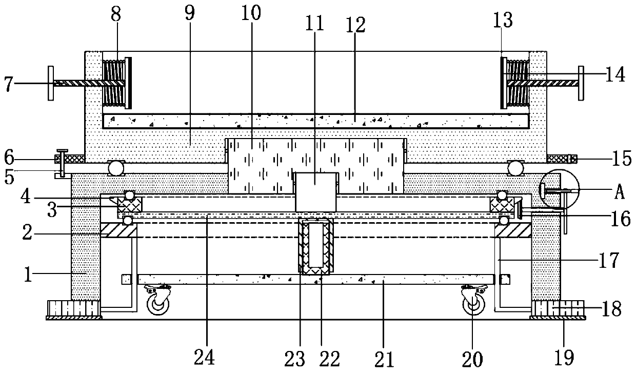
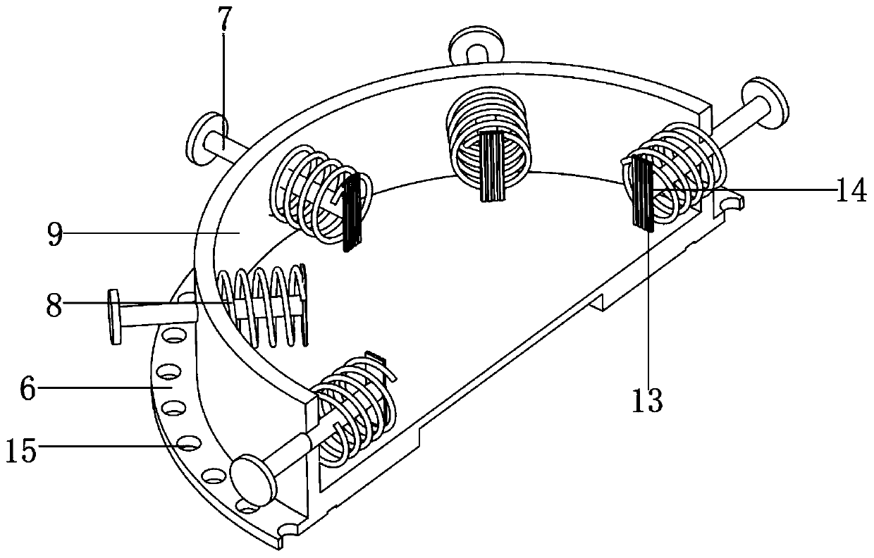
[0029] refer to Figure 1-4 , a fixed base for electromechanical engineering, including a fixed round base 1 and a cylinder base 9, the top of the fixed round base 1 is welded with a fixed cylinder 10 that is rotationally connected with the cylinder base 9 through a bearing, and the bottom end of the fixed round base 1 is open Cavity, the cavity is equipped with a lifting and moving mechanism, and the cylinder seat 9 is equipped with a fixing mechanism, the lifting and moving mechanism includes a rotating plate 24 and a fixed ring plate 2 welded to the inner wall of the cavity, and the top edge of the fixed ring plate 2 is welded with The annular plate 3, the opposite side of the annular plate 3 and the fixed round seat 1 and the rotating plate 24 and the fixed ring plate 2 are all provided with an annular groove 1, and the inner walls of the corresponding two annular grooves 1 are rollingly connected with balls 1 distributed equidistantly. , the center of the bottom of the ro...
Embodiment 2
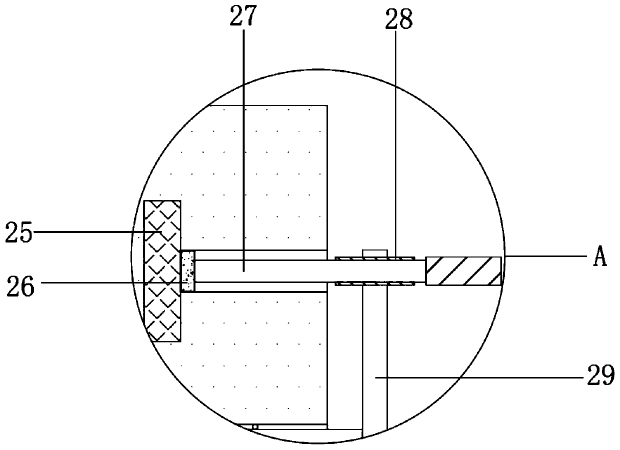
[0039] refer tofigure 1 and Figure 4 , a fixed base for electromechanical engineering. Compared with Embodiment 1, this embodiment also includes a slider 28 welded to one end of the turntable 29, and the slider 28 is slidably connected to a rocker 27, and the end of the rocker 27 is welded with a magnetic Metal limit block 26.
[0040] Wherein, one side of the fixed round seat 1 is provided with a receiving groove compatible with the magnetic metal stopper 26, and one side of the receiving groove is fixed with a magnetic block 25 by screws, and the magnetic block 25 and the magnetic metal stopper 26 form Magnetic fit.
[0041] When the present invention is in use: through the arrangement of the storage slot, the magnetic block 25 and the magnetic metal limit block 26, the operator can insert the end of the rocker 27 into the storage after turning the turntable 29 through the rocker 27 and driving the conical teeth 16 to rotate. In the slot, the magnetic block 25 and the mag...
PUM
 Abstract
Description
Claims
Application Information