Power equipment infrared thermal imaging monitoring system based on artificial intelligence

A technology for infrared thermal imaging and power equipment, which is applied in measuring devices, optical radiation measurement, radiation pyrometry, etc. The effect of high monitoring accuracy

Inactive Publication Date: 2020-03-24
武汉多谱多勒科技有限公司
View PDF4 Cites 2 Cited by
  • Summary
  • Abstract
  • Description
  • Claims
  • Application Information

AI Technical Summary

Problems solved by technology

[0004] The purpose of the present invention is to propose an artificial intelligence-based infrared thermal imaging monitoring system for power equipment in order to solve the problems of high manual inspection intensity and large errors

Method used


Image

  • Power equipment infrared thermal imaging monitoring system based on artificial intelligence

Examples


Embodiment 1

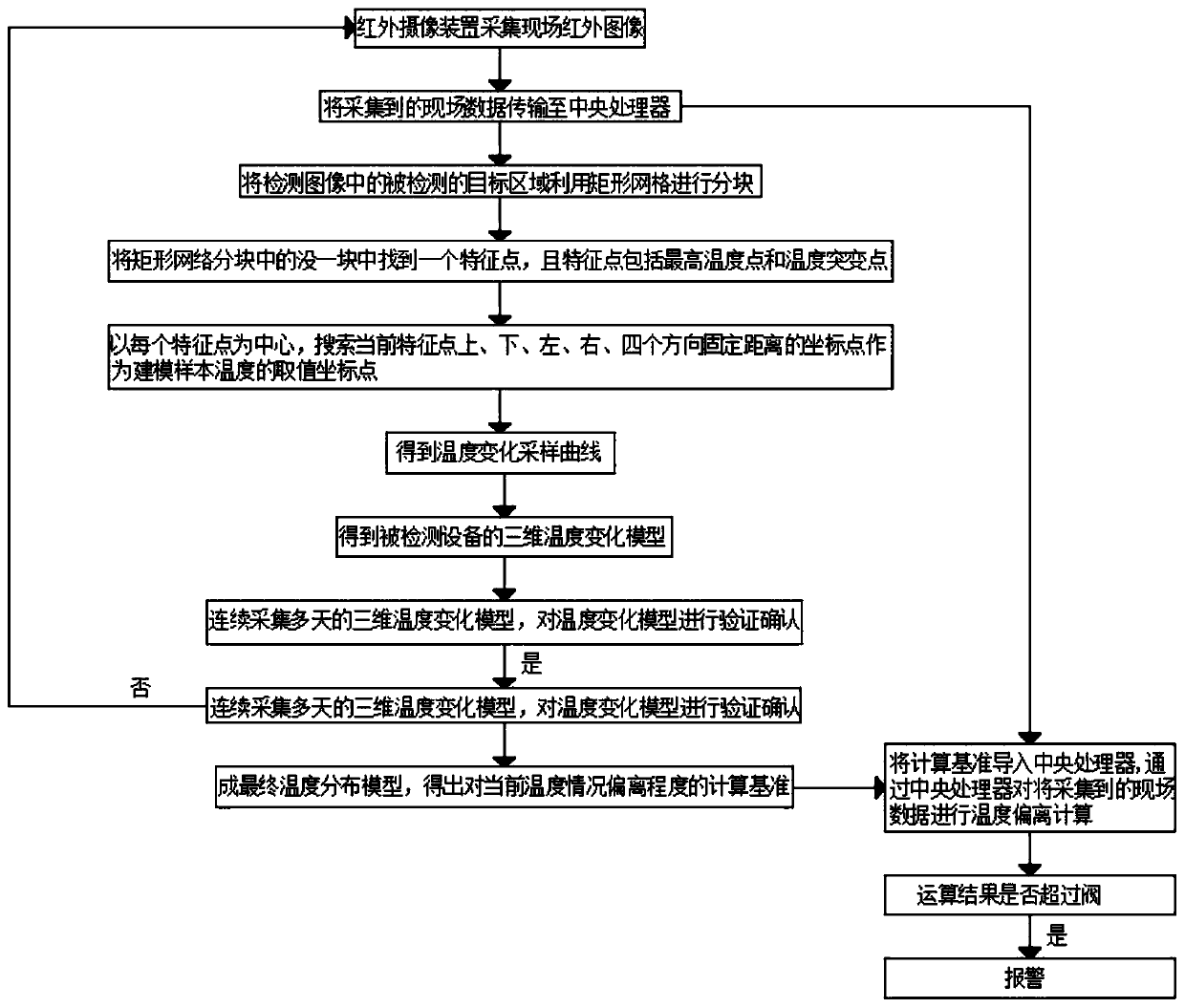
[0031] Example 1, please refer to figure 1 , the present invention provides a technical solution: an artificial intelligence-based infrared thermal imaging monitoring system for power equipment, comprising, characterized in that, comprising the following steps:

[0032] S1. The infrared camera device is installed around the fixed power equipment to collect on-site infrared images;

[0033] S2, transmit the collected field data to the central processing unit through the network;

[0034] S3. Using the infrared image data to analyze the temperature distribution analysis, select the temperature distribution feature points and temperature sample points;

[0035] S4. Collect the temperature values ​​of a group of temperature sample points every certain period of time. Within a period of time, each temperature sample point can obtain a temperature change sampling curve;

[0036] S5. Combining the temperature change sampling curves obtained from all temperature sample points, a thr...

Embodiment 2

[0041] Embodiment two, such as figure 1 As shown, in S3, the detected target area in the detection image is divided into blocks using a rectangular grid. In S3, a feature point is found in each block of the rectangular network block, and the feature points include the highest temperature point and Temperature mutation point, in S3, with each feature point as the center, search for coordinate points with fixed distances in the four directions of up, down, left, right, and four directions of the current feature point as the value coordinate points of the modeling sample temperature, which will be monitored by Carry out rectangular grid blocks in the target area, and establish a corresponding coordinate system. When the system monitors and alarms, the staff only needs to search for data according to the alarm information, and use the established coordinate system for fixed-point processing.

Embodiment 3

[0042] Embodiment three, such as figure 1 As shown, the infrared camera device includes an RGB-D camera and an inertial measurement unit sensor. The threshold value is the temperature mutation point or the highest temperature point of the power equipment. The infrared camera device collects real-time data from the power equipment and transmits the collected data in real time. To the central processing unit, through the central processing unit real-time calculation, if the calculation temperature exceeds the threshold, the over-temperature alarm will reduce human error and labor intensity.

[0043] Working principle: When in use, the infrared camera device is used to continuously collect infrared images on the site, and the temperature distribution characteristic points and temperature sample points are selected through temperature distribution analysis, and the corresponding coordinates are established by making rectangular grid blocks in the monitored target area System, base...


PUM


Abstract

The invention discloses a power equipment infrared thermal imaging monitoring system based on artificial intelligence, and the system comprises the following steps: S1, enabling an infrared camera device to be installed at the periphery of fixed power equipment, and collecting an on-site infrared image; S2, transmitting the acquired field data to a central processing unit through a network; S3, analyzing temperature distribution by utilizing the infrared image data, and selecting temperature distribution characteristic points and temperature sample points; s4, collecting temperature values ofa group of temperature sample points at regular intervals, and obtaining a temperature change sampling curve for each temperature sample point in a period of time domain, and S5, synthesizing the temperature change sampling curves obtained by all the temperature sample points to obtain a three-dimensional temperature change model of the detected equipment. According to the invention, the monitoreddata is transmitted to the central processing unit in real time, real-time operation is carried out through the central processing unit, if the operation temperature exceeds the threshold value, an over-temperature alarm is given, and personal errors and manual labor intensity are reduced.

Description

technical field [0001] The invention relates to the technical field of infrared thermal imaging devices, in particular to an artificial intelligence-based infrared thermal imaging monitoring system for power equipment. Background technique [0002] At present, infrared thermal imaging devices are used for power equipment monitoring, usually manually carrying mobile handheld devices for periodic inspections, or through the network monitoring system platform, using robot inspections to realize remote real-time monitoring of the site, timely detection of temperature abnormalities, and sending out alarm signals . [0003] The use of infrared mobile equipment to manually inspect the work is intensive and the monitoring cycle is long. It is easy to cause omissions or errors during the inspection process. The network monitoring system must continue to manually participate in the real-time observation of the working status of the equipment. Manual real-time monitoring has a large hu...

Claims


Application Information

Patent Timeline
Patent Type & Authority Applications(China)
IPC IPC(8): G01J5/00
CPCG01J5/00G01J2005/0077
Inventor 孙国强
Owner 武汉多谱多勒科技有限公司
Why Eureka
Try Eureka