Millimeter wave radar installation position calibration device and method

A millimeter-wave radar and installation location technology, applied in the field of computer vision, can solve the problems of troublesome operation, great influence of environmental perception, large target position error of millimeter-wave radar, etc., and achieves the effect of high use value and convenient calibration.

Pending Publication Date: 2020-03-24
CHONGQING CHANGAN AUTOMOBILE CO LTD
View PDF12 Cites 9 Cited by
  • Summary
  • Abstract
  • Description
  • Claims
  • Application Information

AI Technical Summary

Problems solved by technology

[0003] Millimeter-wave radars have high requirements on the accuracy of the installation position. If the installation position deviation of the millimeter-wave radar is large, the target position detected by the millimeter-wave radar will have a large error; in addition, the millimeter-wave radars produced by domestic and foreign millimeter-wave radar manufacturers have A certain angle deviation, and this deviation is difficult to completely eliminate at present
These deficiencies have a great impact on environmental perception in driverless car technology
[0004] CN109239685A discloses a calibration device and a calibration method for the installation position of a vehicle-mounted millimeter-wave radar, which can calibrate the installation position of the millimeter-wave radar, but the calibration method is relatively complicated, and after calibration, it needs to be based on the calculated installation attitude of the millimeter-wave radar The deviation, adjusting the installation position of the millimeter-wave radar, the operation is troublesome

Method used


Image

  • Millimeter wave radar installation position calibration device and method
  • Millimeter wave radar installation position calibration device and method
  • Millimeter wave radar installation position calibration device and method

Examples


Embodiment Construction

[0026] The present invention will be described in detail below in conjunction with the accompanying drawings.

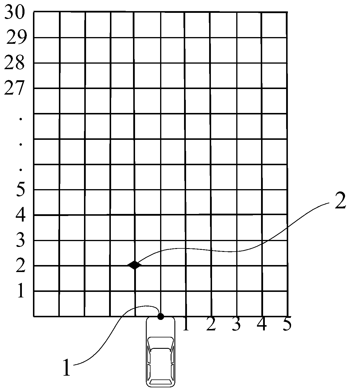
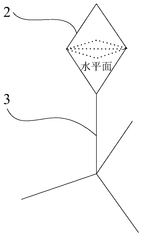
[0027] Such as figure 1 , figure 2 The calibration device for the installation position of the millimeter-wave radar shown includes millimeter-wave radar 1, a corner reflector 2 capable of reflecting millimeter waves, a processor, and a calibration site marked with a distance mark. The calibration site is a rectangular grid site of 10m*30m , the size of each square is 1m*1m. According to different functional requirements, the installation position of the millimeter-wave radar 1 is also different. In this embodiment, the millimeter-wave radar 1 is installed in the center of the front bumper of the vehicle, the millimeter-wave radar 1 is located at the origin of the calibration site, and the corner reflector 2 passes through the bracket 3 Placed in the calibration site and within the detection range of the millimeter-wave radar 1, the true position (including the la...


PUM


Abstract

The invention discloses a millimeter wave radar installation position calibration device and method. The device comprises a millimeter wave radar installed on a vehicle, a corner reflector capable ofreflecting millimeter waves, a processor and a calibration site marked with a distance identifier, the millimeter wave radar is located in the calibration site, and the corner reflector is placed in the calibration site through a support and located in the detection range of the millimeter wave radar. According to the method, the recorded real position of a corner reflector and the position of thecorner reflector detected by the corresponding millimeter wave radar are utilized, and calibration parameters of the installation position of the millimeter wave radar are solved for a target function through an LM optimization algorithm based on a g2o graph optimization library. The calibration method is convenient, rapid, easy to operate and relatively good in calibration effect, and has a veryhigh use value in error correction of the millimeter wave radar installation position of the pilotless automobile.

Description

technical field [0001] The invention relates to the field of computer vision, in particular to a device and method for marking the installation position of a millimeter-wave radar. Background technique [0002] With the rapid development of sensor technology and artificial intelligence, driverless car technology has also developed rapidly. Unmanned vehicles mainly include key technologies such as environmental perception, intelligent decision-making and control, among which environmental perception technology is the basic technology of unmanned vehicles. At present, sensors commonly used in environmental perception include cameras, millimeter-wave radars, and lidars. Among them, millimeter-wave radar is a more widely used depth sensor in driverless cars. [0003] Millimeter-wave radars have high requirements on the accuracy of the installation position. If the installation position deviation of the millimeter-wave radar is large, the target position detected by the millime...

Claims


Application Information

Patent Timeline
Patent Type & Authority Applications(China)
IPC IPC(8): G01S7/40
CPCG01S7/4052G01S7/4082
Inventor 熊新立王宽陈剑斌熊周兵梁锋华
Owner CHONGQING CHANGAN AUTOMOBILE CO LTD
Why Eureka
Try Eureka