Assembled high-voltage isolation switch conductive disc and installation method

A high-voltage isolating switch, conductive disc technology, applied in switchgear, electric switch, high-voltage air circuit breaker and other directions, can solve the problems of long maintenance cycle, prolong power failure time, burn out conductive rollers, etc., to reduce power failure maintenance time, The effect of high operational reliability and high mechanical strength

Pending Publication Date: 2020-03-24
STATE GRID CORP OF CHINA +1
View PDF0 Cites 0 Cited by
  • Summary
  • Abstract
  • Description
  • Claims
  • Application Information

AI Technical Summary

Problems solved by technology

[0002] The existing isolating switch contact plate is generally made of PBT plastic material. With the increase of service time, the contact finger plate is easy to age and break, causing the conductive roller to fall off and increasing the loop resistance between the left and right contact plates. , causing heat in the contact parts, excessive temperature and burning of the remaining conductive rollers, which in turn causes problems such as jammed operation of the isolating switch, poor opening and closing, etc. At the same time, due to the increase in use time, it will also cause internal water accumulation, etc.
The original contact finger plate is a non-detachable overall structure. When replacing it, the coupling needs to be disassembled. After the contact finger plate is replaced, the upper conductor needs to be re-mounted and adjusted. The maintenance cycle is long and time-consuming, which seriously prolongs the power outage time.

Method used


Image

  • Assembled high-voltage isolation switch conductive disc and installation method
  • Assembled high-voltage isolation switch conductive disc and installation method
  • Assembled high-voltage isolation switch conductive disc and installation method

Examples


Embodiment Construction

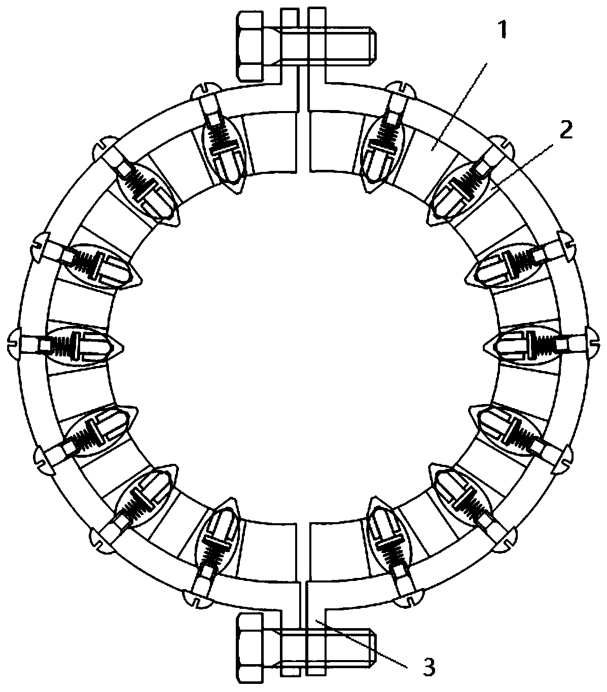
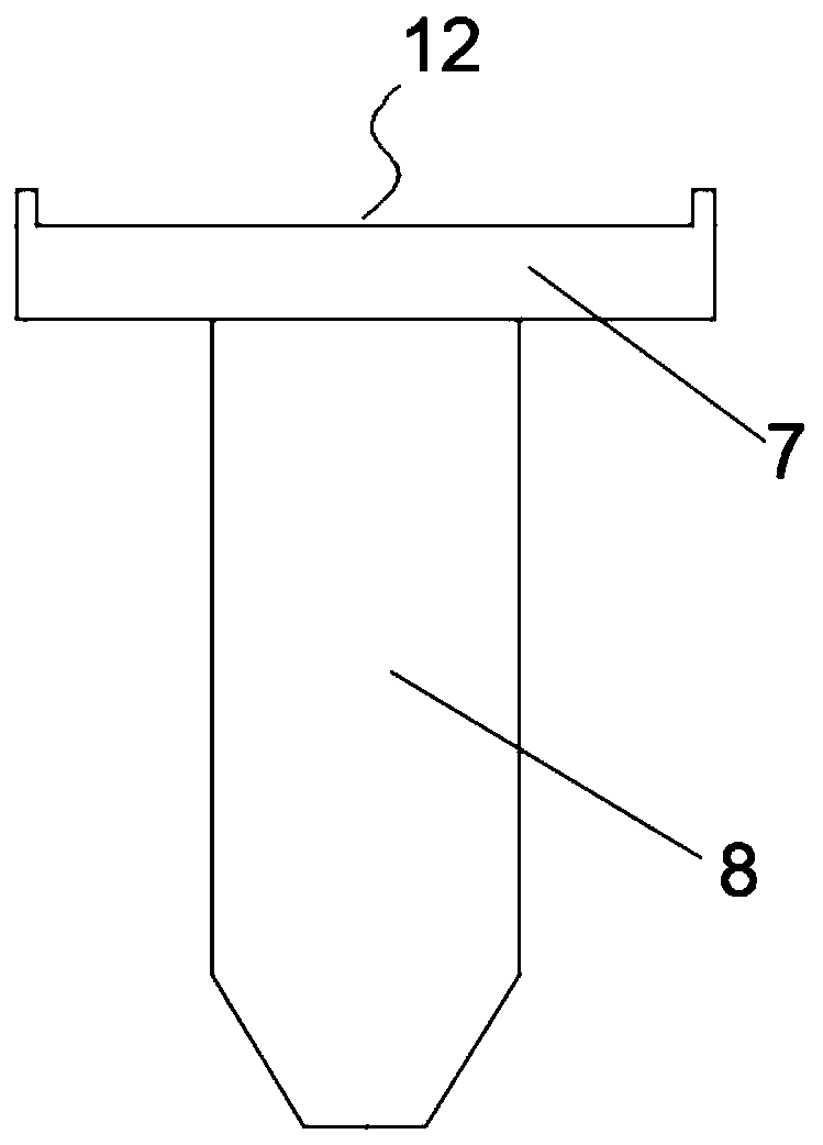
[0032] figure 1 It is a schematic diagram of the first structure of the present invention; figure 2 It is a structural schematic diagram of the conductive roller mechanism of the present invention; image 3 It is a top view of the adjusting bolt of the present invention; as shown in the figure; a conductive plate of an assembled high-voltage isolating switch, including two semi-disc mounting seats 1 that are used in conjunction with each other and can be embraced into a circular structure, and the semi-disc mounting seat 1 A plurality of installation holes 2 are arranged along the radial direction of the circumference, and a conductive roller mechanism is arranged in the installation hole 2; The guide seat used, the spring 5 arranged at the end of the guide seat, and the adjusting bolt 4 used to adjust the compression of the spring 5, the conductive plate of the assembled high-voltage isolating switch of this technical solution can be flexibly disassembled without hoisting t...


PUM


Abstract

The invention discloses an assembled high-voltage isolation switch conductive disc which comprises two semi-circular disc mounting bases which are used in cooperation with each other and can be combined into a circular structure, a plurality of mounting holes are formed in the semi-circular disc mounting bases in the circumferential radial direction, and conductive roller mechanisms are arranged in the mounting holes. Each conductive roller mechanism comprises a touch roller head arranged at the bottom of the mounting hole, a guide seat matched with the touch roller head for use, a spring arranged at the end part of the guide seat, and an adjusting bolt for adjusting the compression amount of the spring; according to the technical scheme, on one hand, rapid installation can be realized, the power failure time is reduced, and the human, financial and material costs are reduced; on the other hand, operation reliability is high, corrosion resistance is high, mechanical strength is high, deformation is not likely to happen, the overhaul period is long, and maintenance is convenient.

Description

technical field [0001] The invention relates to the field of electric outdoor tools, in particular to an assembled high-voltage isolating switch conducting plate and an installation method. Background technique [0002] The existing isolating switch contact plate is generally made of PBT plastic material. With the increase of service time, the contact finger plate is easy to age and break, causing the conductive roller to fall off and increasing the loop resistance between the left and right contact plates. , causing heating of the contact parts, excessive temperature and burning of the remaining conductive rollers, which in turn causes problems such as jammed operation of the isolating switch, poor opening and closing, and internal water accumulation due to the increase in use time. The original contact finger plate is a non-detachable overall structure. When replacing it, the coupling needs to be disassembled. After the contact finger plate is replaced, the upper conductor...

Claims


Application Information

Patent Timeline
Patent Type & Authority Applications(China)
IPC IPC(8): H01H31/02H01H1/58H02B3/00
CPCH01H1/58H01H31/023H01H31/026H02B3/00
Inventor 王振亚李汶江陈铁江帆南航熊浩刘钢赵凯谢林涛杨华忠刘力哥
Owner STATE GRID CORP OF CHINA
Why Eureka
Try Eureka