Kirschner wire clamping device and drilling device

A clamping device and Kirschner wire technology, applied in bone drill guidance, medical science, surgery, etc., can solve the problem of Kirschner wire breakage, the inability to accurately grasp the clamping force of Kirschner wire, and affect the effect of bone tissue surgery and other issues to achieve the effect of avoiding negative impact

Pending Publication Date: 2020-03-27
北京精准大艾机器人科技有限公司
View PDF1 Cites 6 Cited by
  • Summary
  • Abstract
  • Description
  • Claims
  • Application Information

AI Technical Summary

Problems solved by technology

[0004] However, manually clamping the Kirschner wires often cannot accurately grasp the clamping force of the Kirschner wires. Too tight or over-feeding clamping forces will affect the surgical effect of bone tissue surgery, and manual clamping Tight Kirschner wires also cannot guarantee a constant clamping force while drilling
Since the Kirschner wire rotates at high speed when drilling, any instantaneous change in clamping force will exert an instantaneous lateral moment on the high-speed rotating Kirschner wire, and this lateral moment, even if it is small, will affect the high-speed rotating Kirschner wire. Negative impact of needles, even lead to breakage of Kirschner wires
In addition, it is also challenging to realize the automatic clamping of the Kirschner wire in the small internal space of the Kirschner wire holding device

Method used


Image

  • Kirschner wire clamping device and drilling device
  • Kirschner wire clamping device and drilling device
  • Kirschner wire clamping device and drilling device

Examples


Embodiment Construction

[0027] Specific embodiments of the present invention will be described below with reference to the accompanying drawings, some of which are shown in the accompanying drawings. It should be understood that the embodiments shown in the drawings are exemplary only and should not be considered as limiting the invention.

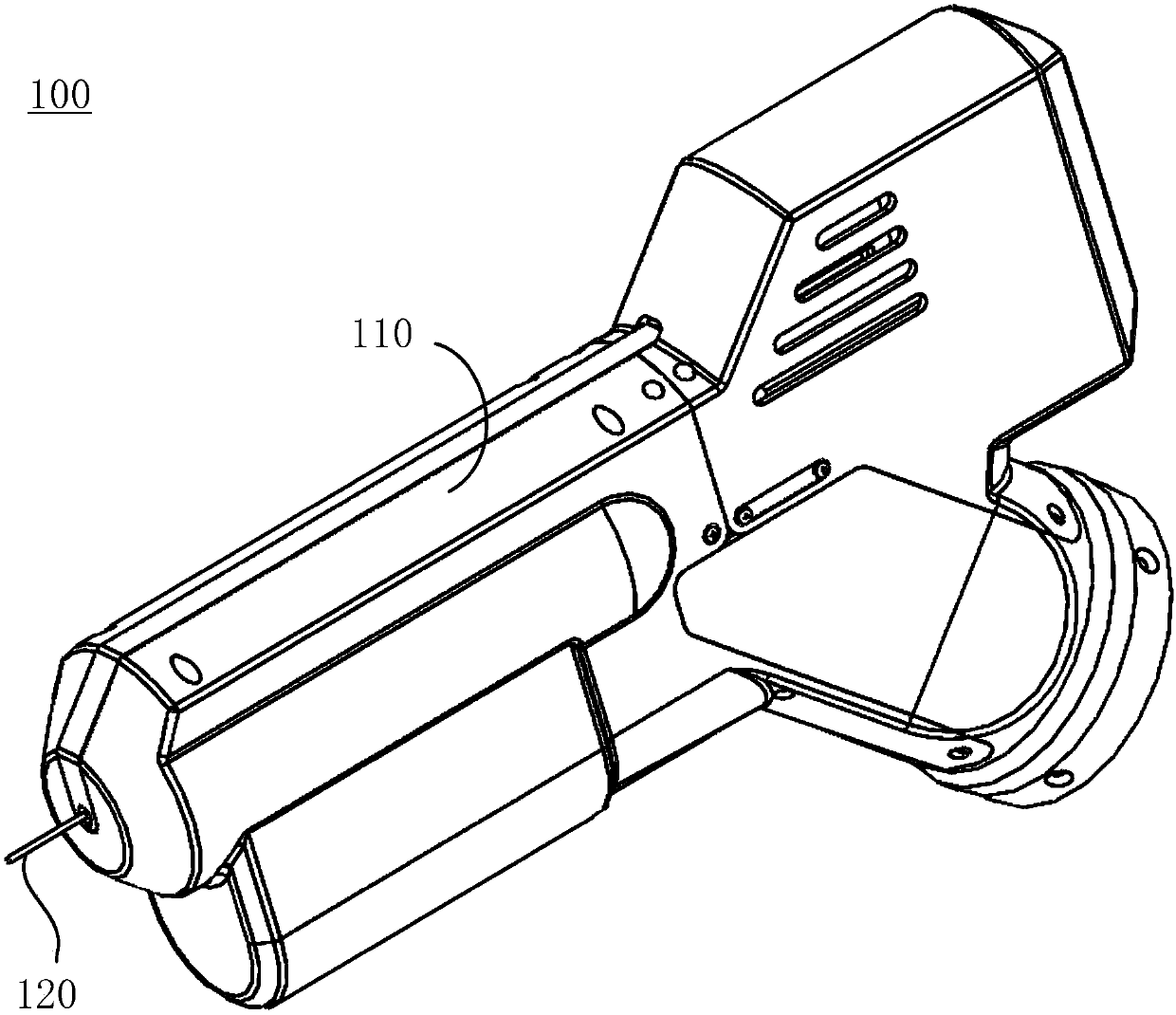
[0028] See figure 1 , figure 1 A schematic perspective view of the Kirschner wire clamping device 100 according to an embodiment of the present invention is shown. The clamping device 100 includes a housing 110 for accommodating various components of the clamping device 100 described below, wherein a Kirschner wire 120 extends out of the housing 110 from an opening at the front end of the housing 110 for performing bone surgery. tissue surgery. The clamping structure for clamping the Kirschner wire in the clamping device 100 will be described in detail below.

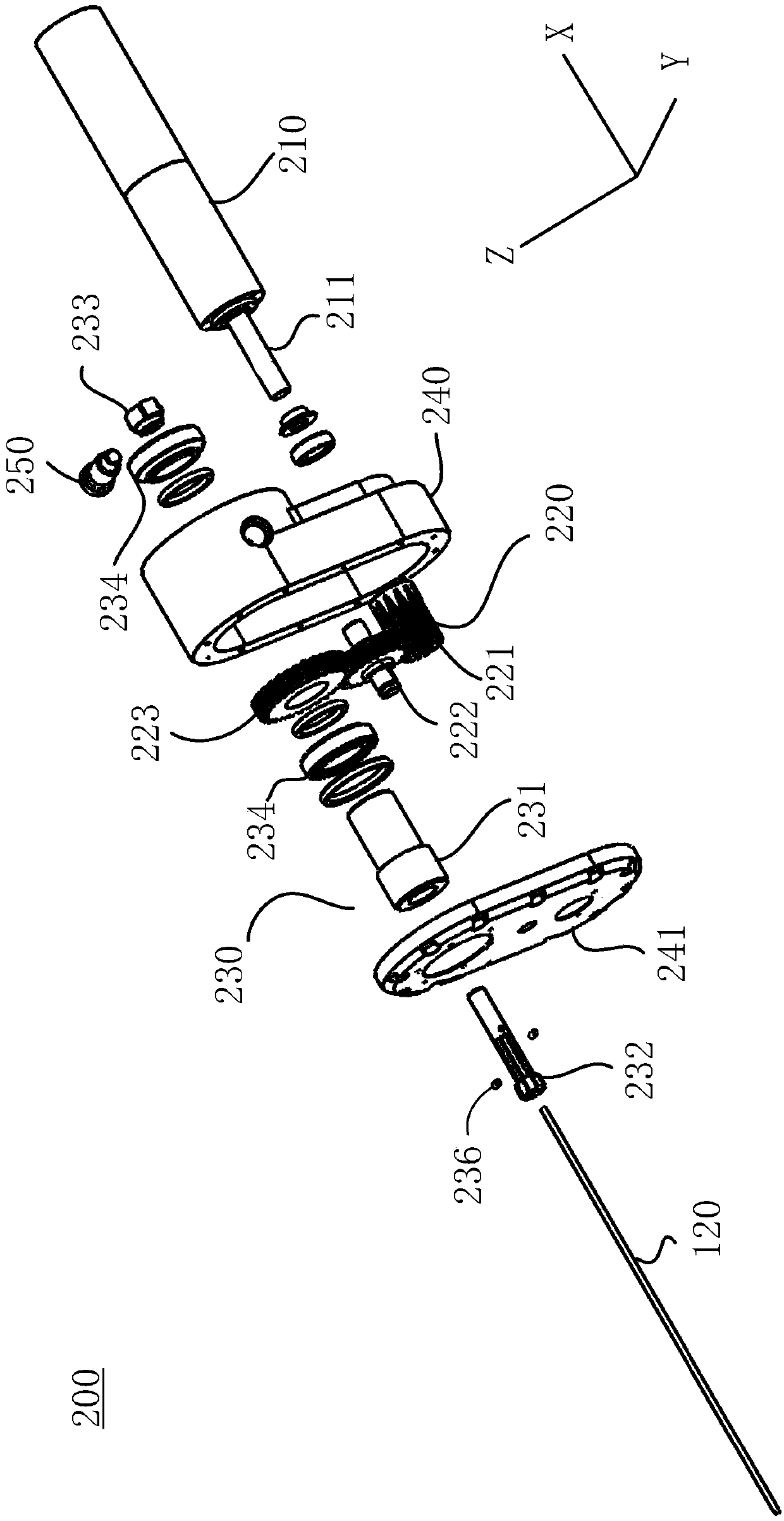
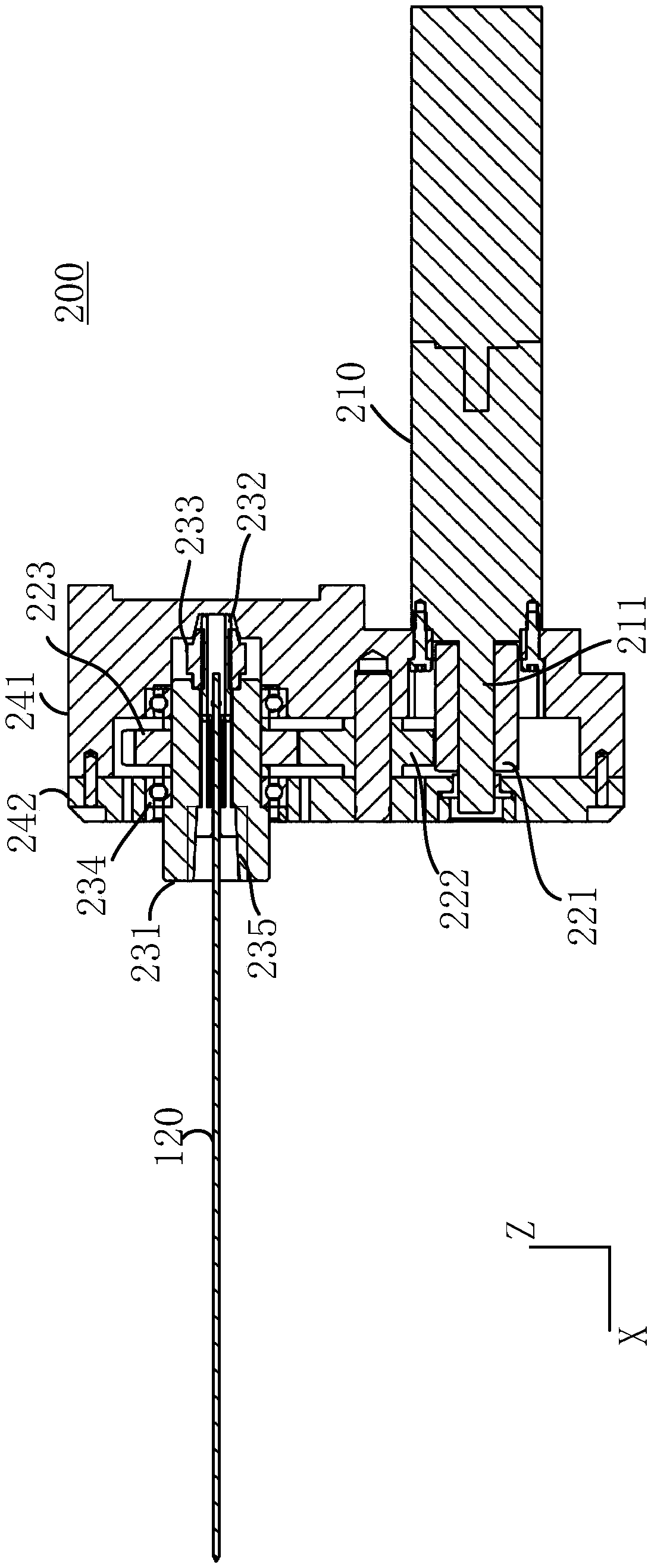
[0029] Please continue to see Figure 2 to Figure 4 , Figure 2 to Figure 4 An exploded view, a s...


PUM


Abstract

The present invention discloses a Kirschner wire clamping device. The Kirschner wire clamping device comprises an outer shell, and a motor, a gear set and a clamping head mechanism arranged in the outer shell, the gear set is connected with a driving shaft of the motor, and the clamping head mechanism comprises a first sleeve, a second sleeve and a nut; the first sleeve is connected with the gearset and also provided with a front end and a rear end; the second sleeve is sleeved in the first sleeve and matched with a conical surface of the first sleeve, besides, the second sleeve is provided with a first end and a second end, Kirschner wire penetrates through the second sleeve and extends through the first end of the second sleeve and out of the front end of the first sleeve, and the second end of the second sleeve extends out of the rear end of the first sleeve; and the nut is arranged at the rear end of the first sleeve and detachable from the first sleeve, and besides, the second end of the second sleeve is screwed into the nut. A Kirschner wire drilling device is provided with the Kirschner wire clamping device and a pushing device, and the pushing device is connected with theKirschner wire clamping device to apply pushing force to the Kirschner wire clamping device.

Description

technical field [0001] The invention relates to the technical field of medical instruments, in particular to a Kirschner wire clamping device and a Kirschner wire drilling device with the Kirschner wire clamping device. Background technique [0002] In bone tissue surgery, it is often necessary to use Kirschner for positioning and other operations on bone tissue. Kirschner wires are small in diameter and long in length, generally no more than 4mm in diameter, and more than 200mm in length, so the Kirschner wires need to be clamped on the electric drilling device through a special clamping device. When drilling, the Kirschner wire extends out of the front end of the clamping device for a certain length. After drilling into a certain depth, loosen the clamping device so that more lengths of the Kirschner wire extend out of the front end of the clamping device, and then re-clamp the Kirschner wire , and then drill a certain depth, and so on, until the Kirschner wire drills to ...

Claims


Application Information

Patent Timeline
Patent Type & Authority Applications(China)
IPC IPC(8): A61B17/16A61B17/17
CPCA61B17/1604A61B17/17
Inventor 帅梅秦蓁
Owner 北京精准大艾机器人科技有限公司
Why Eureka
Try Eureka