Casting equipment with a heat dissipation function for metal products

A technology of metal products and casting equipment, which is applied in the field of metal product manufacturing, can solve the problems of reducing the casting efficiency of hydraulic casting machines, reducing the practicality of hydraulic casting machines, and increasing the blockage of feeding pipes, so as to speed up the cooling and forming time and speed up the air flow. The effect of increasing circulation speed and improving energy saving and environmental protection

Inactive Publication Date: 2020-03-27
科曼空气技术(深圳)有限公司
View PDF10 Cites 3 Cited by
  • Summary
  • Abstract
  • Description
  • Claims
  • Application Information

AI Technical Summary

Problems solved by technology

[0003] When the existing hydraulic casting machine is casting, it needs to wait for the casting liquid to cool naturally, which consumes a lot of time and reduces the casting efficiency of the hydraulic casting machine. Not only that, the existing hydraulic casting machine is waiting for the casting liquid to cool naturally At the same time, the casting liquid in the feeding pipe will also solidify, thereby increasing the probability of blockage in the feeding pipe and reducing the practicability of the existing hydraulic casting machine

Method used


Image

  • Casting equipment with a heat dissipation function for metal products
  • Casting equipment with a heat dissipation function for metal products
  • Casting equipment with a heat dissipation function for metal products

Examples


Embodiment Construction

[0024] The present invention is described in further detail now in conjunction with accompanying drawing. These drawings are all simplified schematic diagrams, which only illustrate the basic structure of the present invention in a schematic manner, so they only show the configurations related to the present invention.

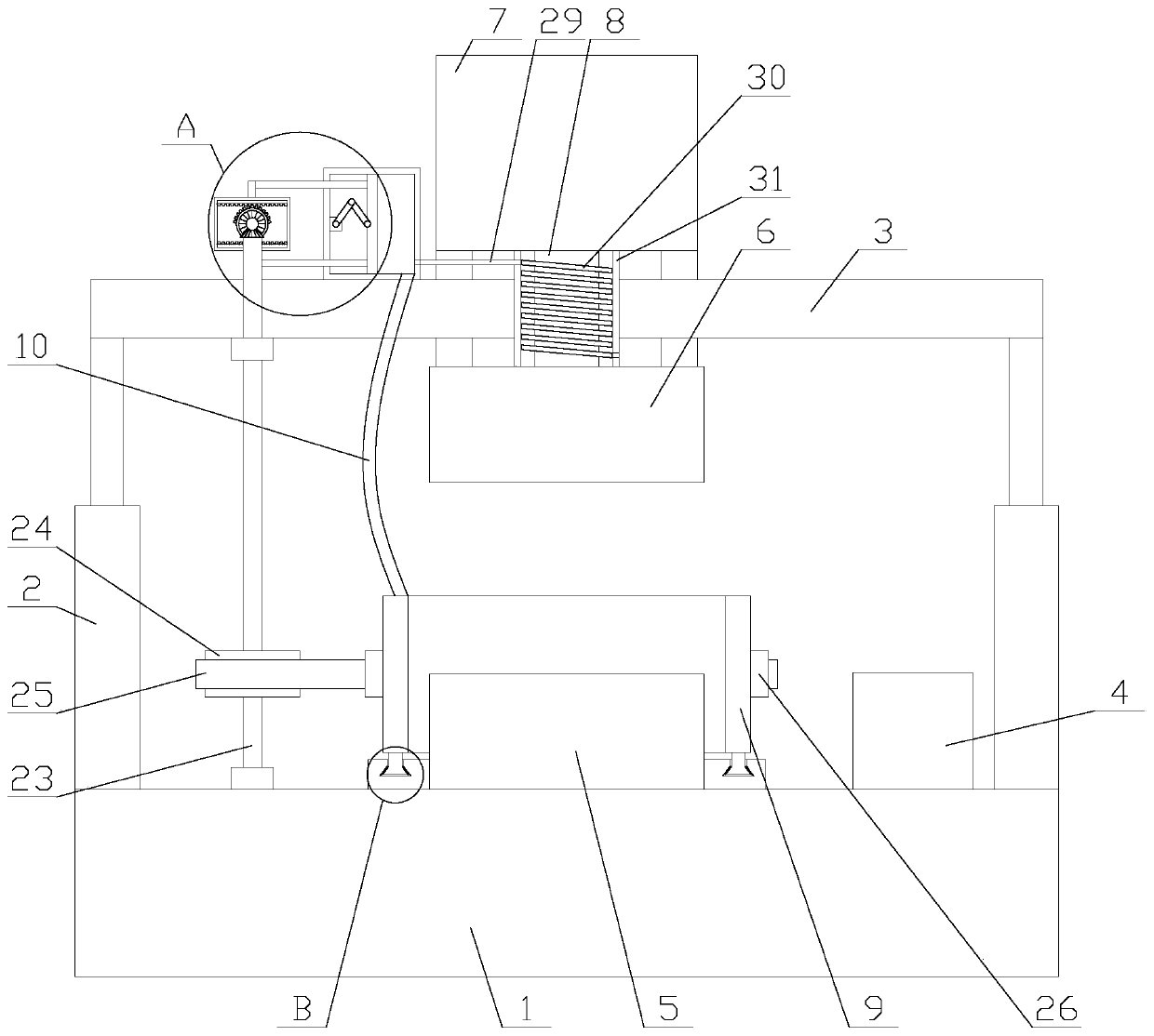
[0025] Such as figure 1 As shown, a casting equipment with heat dissipation function for metal products, including a base 1, a bottom mold 5, a top mold 6, a support plate 3, a connection box 7, a feeding pipe 8, a control panel 4 and two hydraulic cylinders 2 , the two hydraulic cylinders 2 are respectively fixed at the two ends above the base 1, the gas rods of the two hydraulic cylinders 2 are respectively connected with the two ends of the support plate 3, the top mold 6 is fixed below the support plate 3, and the The bottom mold 5 is fixed on the top of the base 1, the top mold 6 and the bottom mold 5 are arranged oppositely, the connection box 7 is fixe...


PUM


Abstract

The invention relates to casting equipment with a heat dissipation function for metal products. The casting equipment comprises a base, a bottom die, a top die, a support plate, a connecting box, a feeding pipe, a control panel and two hydraulic cylinders. The casting equipment further comprises a heat dissipation mechanism and an anti-blocking mechanism. The heat dissipation mechanism comprises an air suction box, a hose, an air cylinder, a piston, a driving assembly, a connecting assembly, a transmission assembly and a limiting assembly. The anti-blocking mechanism comprises a heat preservation pipe and a connecting pipe. According to the casting equipment with the heat dissipation function for the metal products, the heat dissipation mechanism is arranged to dissipate hot air around thebottom die away, so that the air circulation speed around the bottom die is accelerated, a heat dissipation function is achieved, cooling and molding time of casting products is accelerated and the efficiency of casting is improved; and through the anti-blocking mechanism, the feeding pipe is heated and subjected to heat preservation work, and the situation that casting liquid in the feeding pipeis cooled and solidified, and consequently, the feeding pipe is blocked is avoided, so that the anti-blocking function is achieved, and the practicability of the equipment is improved.

Description

technical field [0001] The invention relates to the field of metal product manufacturing, in particular to a casting device for metal products with heat dissipation function. Background technique [0002] Strictly speaking, casting equipment is a machine that uses this technology to smelt metals into liquids that meet certain requirements and pour them into molds, and obtain castings with predetermined shapes, sizes and properties after cooling, solidification, and cleaning. A hydraulic casting machine is a casting device that operates through hydraulic pressure as a driving source. [0003] When the existing hydraulic casting machine is casting, it needs to wait for the casting liquid to cool naturally, which consumes a lot of time and reduces the casting efficiency of the hydraulic casting machine. Not only that, the existing hydraulic casting machine is waiting for the casting liquid to cool naturally At the same time, the casting liquid in the feeding pipe will also sol...

Claims


Application Information

Patent Timeline
Patent Type & Authority Applications(China)
IPC IPC(8): B22D17/00B22D17/22B22D17/20
CPCB22D17/00B22D17/2038B22D17/2218
Inventor 武桂英
Owner 科曼空气技术(深圳)有限公司
Why Eureka
Try Eureka