
Rod material derusting device for bearing production

A technology for bearing production and bar stock, applied in metal processing equipment, grinding/polishing equipment, grinding machine parts, etc., can solve the problems of low work efficiency, delayed production efficiency, time-consuming and laborious, etc.

Pending Publication Date: 2020-03-27
宿州海纳百川轴承有限公司
View PDF0 Cites 0 Cited by
  • Summary
  • Abstract
  • Description
  • Claims
  • Application Information

AI Technical Summary

Problems solved by technology

[0002] Due to the unreasonable storage of the bars required in the production of bearings, rust will occur on the surface. The traditional rust removal method, that is, manual grinding with sandpaper, has low work efficiency, time-consuming and labor-intensive problems, and delays production efficiency.

Method used


Image

  • Rod material derusting device for bearing production
  • Rod material derusting device for bearing production
  • Rod material derusting device for bearing production

Examples


Embodiment Construction

[0014] In order to make the technical means, creative features, goals and effects achieved by the present invention easy to understand, the present invention will be further described below in conjunction with specific embodiments.

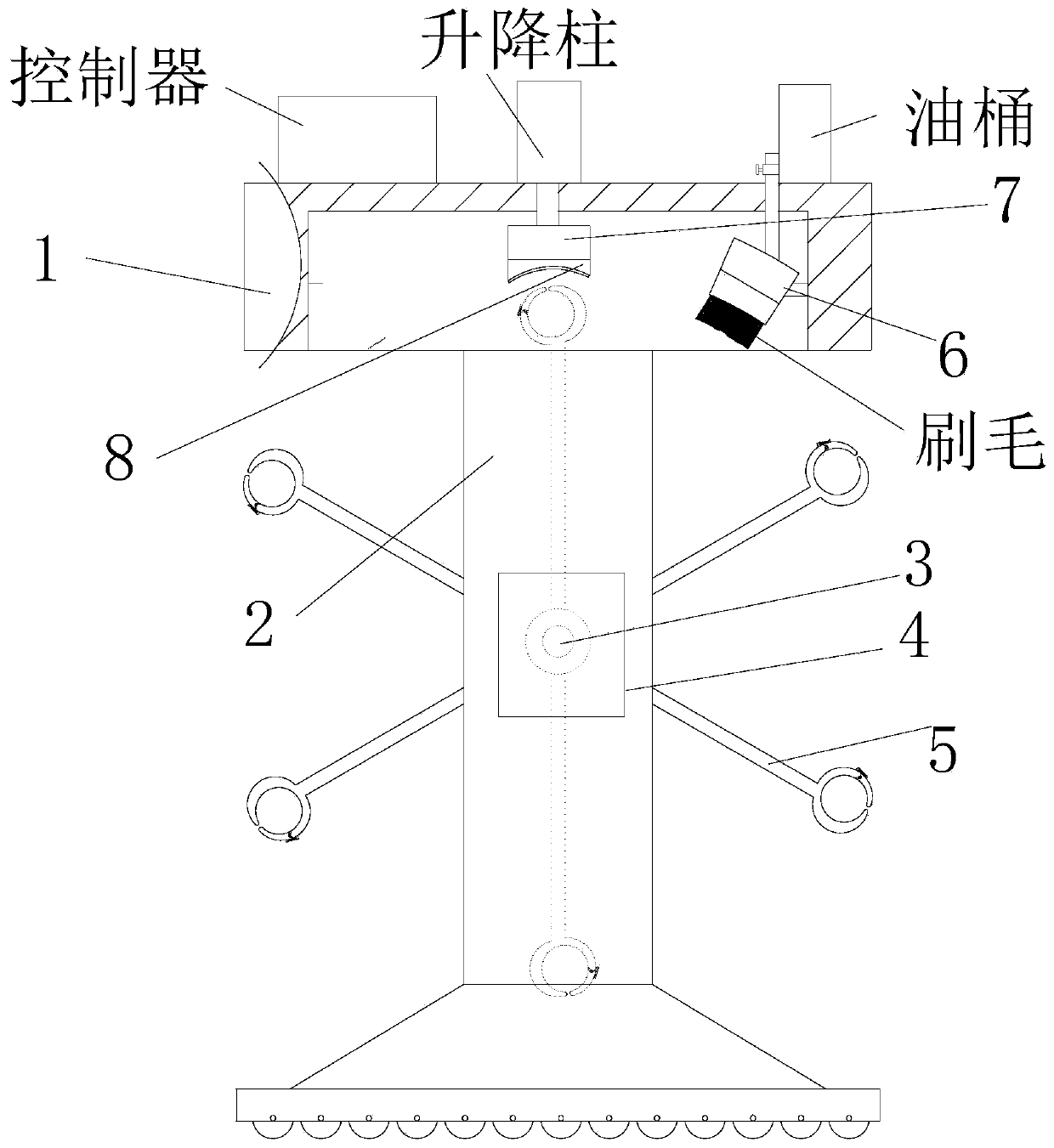
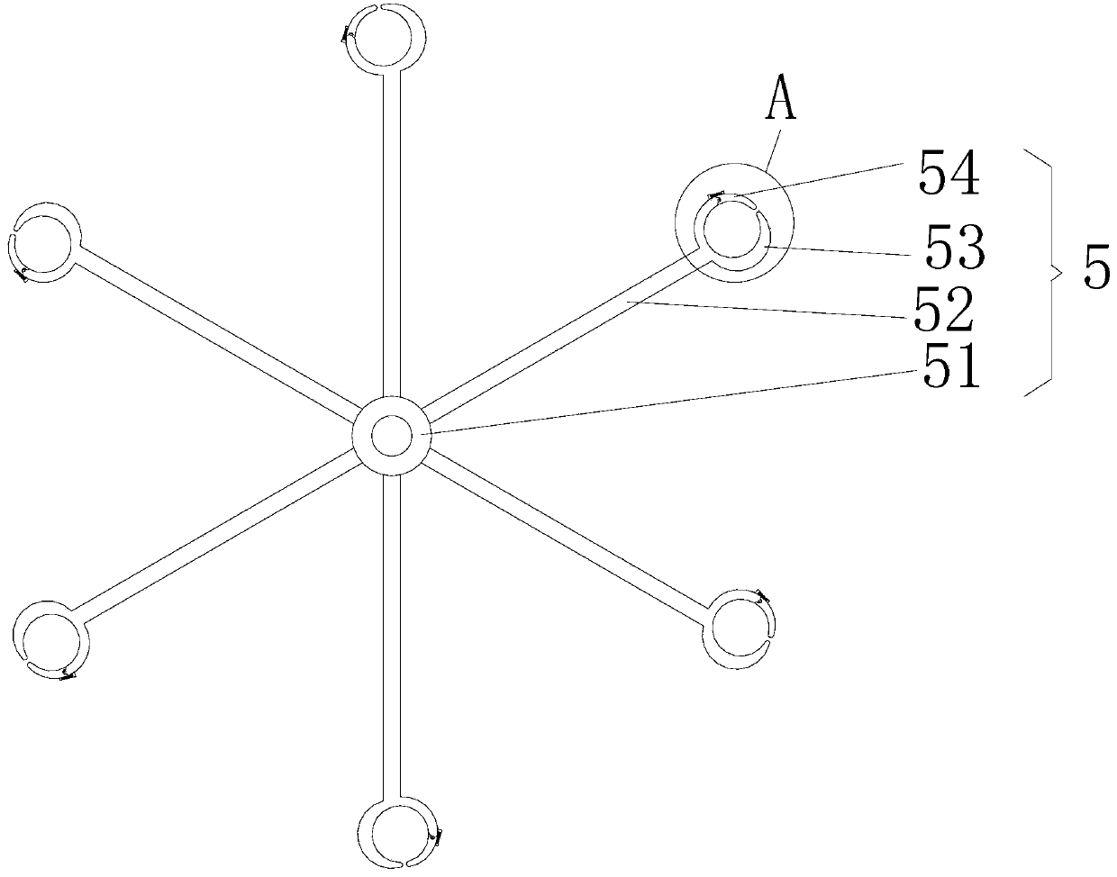
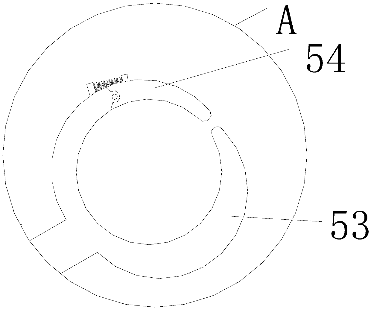
[0015] like Figure 1-3 As shown, a bar derusting equipment used for bearing production includes a top base 1, the bottom of the top base 1 is fixedly connected with a support 2 at a symmetrical position close to the front and back of the top base 1, and the bottom end of the support 2 is provided with a movable seat , and the bottom of the mobile seat is provided with casters, and the brackets 2 are provided with a rotating shaft 3 in the middle of one side close to each other. The rotating shaft 3 extends to the outside of the front outer wall of the top seat 1. Geared motor 4, the end of the output shaft of the geared motor 4 is connected to the rotating shaft 3 through a coupling and a gear, and the outer surface of the rotating shaft 3 locate...


PUM


Abstract

The invention discloses a rod material derusting device for bearing production. The device comprises an ejection seat, wherein supports are fixedly connected to the symmetrical positions, close to thefront face and the back face of the ejection seat, of the bottom of the ejection seat, the parts, located between the supports, and at the symmetrical positions close to the front face and the back face of the ejection seat, of the outer surface of a rotating shaft are fixedly connected with rotating devices, a brush seat is fixedly connected with the right side of the inner surface of the ejection seat, a controller is arranged at the top of the ejection seat, and the controller is electrically connected with a lifting column and a reduction motor; and each rotating device comprises a shaftseat, wherein plural connecting rods are arranged on the outer surface of the shaft seat, and the end, close to the shaft seat, of a three-quarters ring is rotationally connected with a limiting clawthrough a returning spring. According to the device, the controller is controlled to control the reduction motor to drive the rotating devices to rotate to the proper positions, and then to control the lifting column to push abrasive paper at the bottom end of the lifting column to move downwards and attach to a rod material brought up by the rotating devices so that the problems in the backgroundart can be solved.

Description

technical field [0001] The invention relates to the field of bearing equipment, in particular to a bar material derusting equipment used for bearing production. Background technique [0002] Due to the unreasonable storage of the bars required in the production of bearings, rust will be produced on the surface. The traditional method of rust removal, that is, manual grinding with sandpaper, has low work efficiency, time-consuming and labor-intensive problems, and delays production efficiency. Contents of the invention [0003] The main purpose of the present invention is to provide a bar material derusting equipment used for bearing production. The control controller controls the deceleration motor to drive the rotating equipment to rotate to a suitable position, and then controls the lifting column to push the bottom of the lifting column. The sandpaper goes down and sticks to the bar brought up by the rotating equipment, which can effectively solve the problems in the ba...

Claims


Application Information

Patent Timeline
IPC IPC(8): B24B27/00B24B27/033B24B41/06B24B47/16B24B47/22B24B57/02
CPCB24B27/0023B24B27/0069B24B27/033B24B41/06B24B47/16B24B47/22B24B57/02
Inventor 王宣强
Owner 宿州海纳百川轴承有限公司
Learn More