High-speed efficient drill bit

A high-efficiency and high-speed technology, applied in the direction of stone processing tools, manufacturing tools, stone processing equipment, etc., can solve the problems of difficult discharge and the inability of the drill to work at high speed and high efficiency, and achieve the effect of high speed and high efficiency.

Pending Publication Date: 2020-03-27
GUILIN CHAMPION UNION DIAMOND CO LTD
View PDF0 Cites 5 Cited by
  • Summary
  • Abstract
  • Description
  • Claims
  • Application Information

AI Technical Summary

Problems solved by technology

With the above settings, when the working ring 1 rotates at a high speed, the chips rotate synchronously with the working ring 1 in the discharge port 2, and it is not easy to be disc

Method used


Image

  • High-speed efficient drill bit
  • High-speed efficient drill bit
  • High-speed efficient drill bit

Examples


Embodiment 1

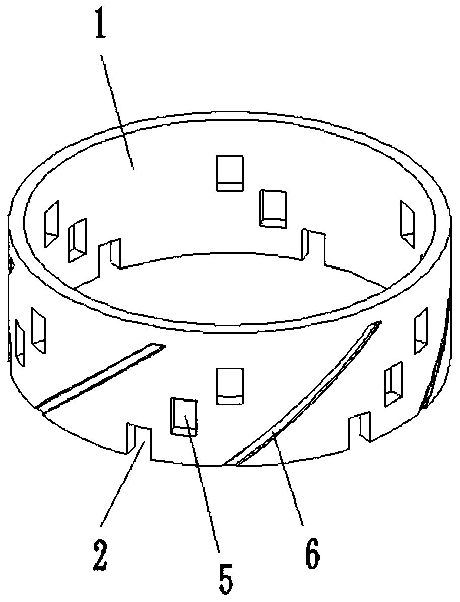
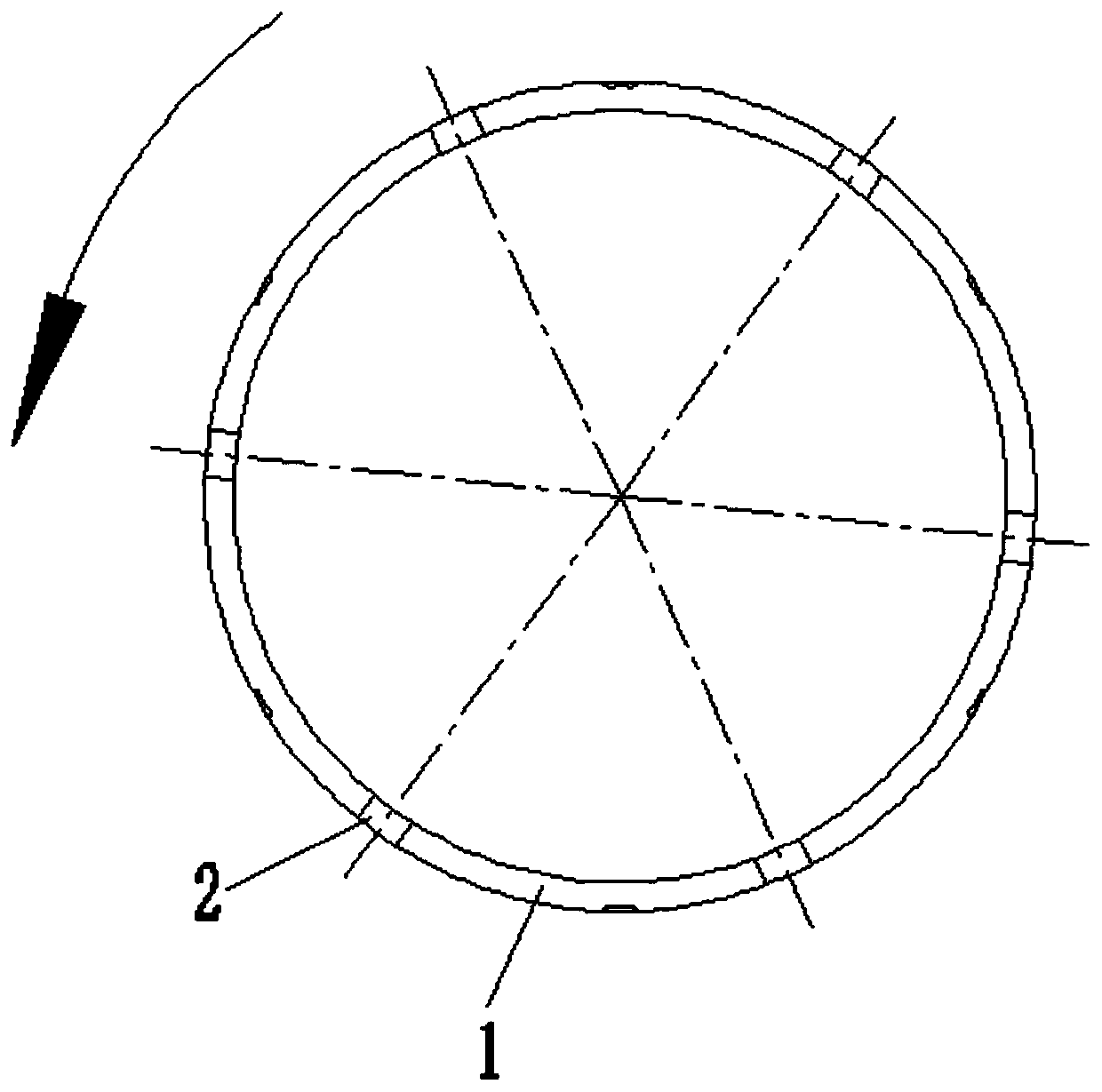
[0048] Such as Figure 4 with 5 As shown, a high-speed and high-efficiency drill bit includes a working ring 1 and a discharge port 2. The working ring 1 has a cylindrical structure, and the discharge ports 2 are arranged in a plurality, which are distributed in a ring shape at the bottom of the side wall of the working ring 1 to discharge scraps when the working ring 1 is rotating and processing. The two sides of the bottom of the discharge port 2 are arranged in parallel, and the center line of symmetry does not pass through the center of the bottom surface of the working ring 1, and the two sides of the bottom of the discharge port 2 are in a spiral shape relative to the center of the bottom surface of the working ring 1. Arranged, and the helical direction is consistent with the rotation direction of the working ring 1. In this embodiment, the chips can be discharged outward along the discharge port 1 under the action of the centrifugal force of the rotation of the worki...

Embodiment 2

[0051] This embodiment mainly changes the structure of the discharge port 2, and the rest is consistent with the first embodiment.

[0052] Such as Image 6 with 7 As shown, the two sides of the bottom of the discharge opening 2 are respectively the first side 3 and the second side 4 in the direction of rotation of the working ring 1, and the first side 3 and the second side The center line of the angle formed by the sides 4 does not pass through the center of the bottom surface of the working ring 1 . Such as Figure 17 As shown, one end of the first side 3 is at the corresponding position on the inner wall of the working ring 1, and the other end of the first side 3 deflects toward the outside of the working ring 1 and in the direction opposite to the rotation direction of the working ring 1. angle α. One end of the second side 4 is at the corresponding position on the inner wall of the working ring 1, and the other end of the second side 4 faces the outside of the worki...

Embodiment 3

[0055] This embodiment mainly changes the structure of the discharge port 2, and the rest is consistent with the first embodiment.

[0056] Such as Figure 10-13 As shown, the two sides of the discharge port 2 are arranged in parallel, and the symmetrical center line of the two sides of the bottom does not pass through the center of the bottom surface of the working ring 1 . The two sides of the discharge port 2 are arranged obliquely relative to the bottom surface of the working ring 1 in the direction of rotation of the working ring 1, and one end of the two sides of the discharge port 2 is at the corresponding position on the inner wall of the working ring 1, The other end is deflected by a preset angle toward the outside of the working ring 1 and in the direction of rotation of the working ring 1 . The top of the discharge port 2 is rounded, and the bottom and top of the spare discharge port 5 are rounded. The rounded corner structure prevents stress concentration and fa...


PUM


Abstract

The invention relates to a high-speed efficient drill bit. The drill bit comprises a working ring and a discharging opening, wherein the working ring is of a cylinder structure, multiple discharging opening rings are annularly distributed at the bottom of the side wall of the working ring so that scraps can be discharged during rotary machining of the working ring, and symmetrical center lines oftwo side edges of the bottom of the discharging opening or the center lines of an included angle formed by the two side edges of the bottom of the discharging opening does not pass through the circlecenter of a bottom face of the working ring. The drill bit is advantaged in that the scraps can be subjected to mechanical thrust of the discharging opening towards an outer side of the working ring along with rotation of the working ring in the discharging opening, the scraps can be discharged from the discharging opening more easily under the action of the mechanical thrust, and that the drill bit can work at high speed and high efficiency is guaranteed.

Description

technical field [0001] The invention relates to the field of processing tools, in particular to a high-speed and high-efficiency drill bit. Background technique [0002] Existing drills such as Figure 1-3 As shown, including working ring 1 and discharge port 2. The working ring 1 is fixed on the lower end of the matrix 7 , and its surface is provided with an abrasive layer such as diamond particles, and the wall thickness of the working ring 1 is greater than that of the matrix 7 . During the processing, the cooling water flows in from the inside of the base body 7 and then flows downward through the gap between the inner wall of the working ring 1 and the glass 8 (a gap for cooling water flow is formed between the diamond particles), and then flows out from the lower end of the working ring 1 toward the outside , and finally discharged upwards through the gap between the outer wall of the working ring 1 and the glass 8 (such as image 3 indicated by the arrow in). Durin...

Claims


Application Information

Patent Timeline
IPC IPC(8): B28D1/14
CPCB28D1/146
Inventor 宋京新龙慧玲梁安宁郭新玲叶勇刘人杰王志勇
Owner GUILIN CHAMPION UNION DIAMOND CO LTD
Why Eureka
Try Eureka