
Strong yarn cleaner of textile machine

A yarn clearer and textile machine technology, applied in textiles and papermaking, fiber cleaning, fiber treatment, etc., can solve the problems of easy-to-damage yarn cleaning effect, etc., and achieve strong and good cleaning effect

Active Publication Date: 2020-03-27
HEFEI C&P NONWOVEN PROD
View PDF5 Cites 0 Cited by
  • Summary
  • Abstract
  • Description
  • Claims
  • Application Information

AI Technical Summary

Problems solved by technology

[0005] A powerful yarn clearer for a textile machine proposed by the present invention aims to solve the problems in the traditional technology that the yarn is easily damaged by blowing the vertical yarn and the cleaning effect is poor by blowing along the yarn.

Method used

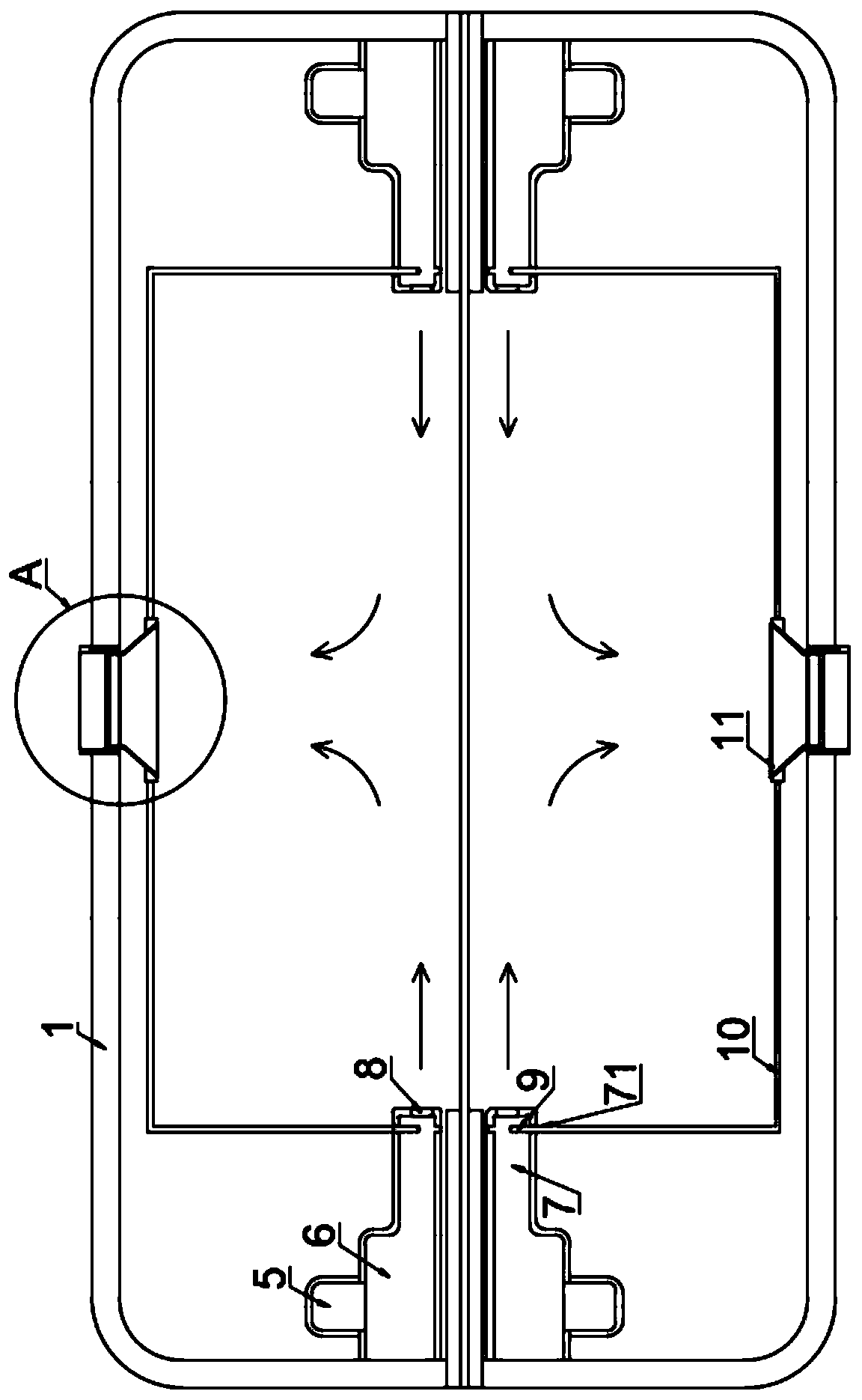

Image

  • Strong yarn cleaner of textile machine
  • Strong yarn cleaner of textile machine
  • Strong yarn cleaner of textile machine

Examples


Embodiment 1

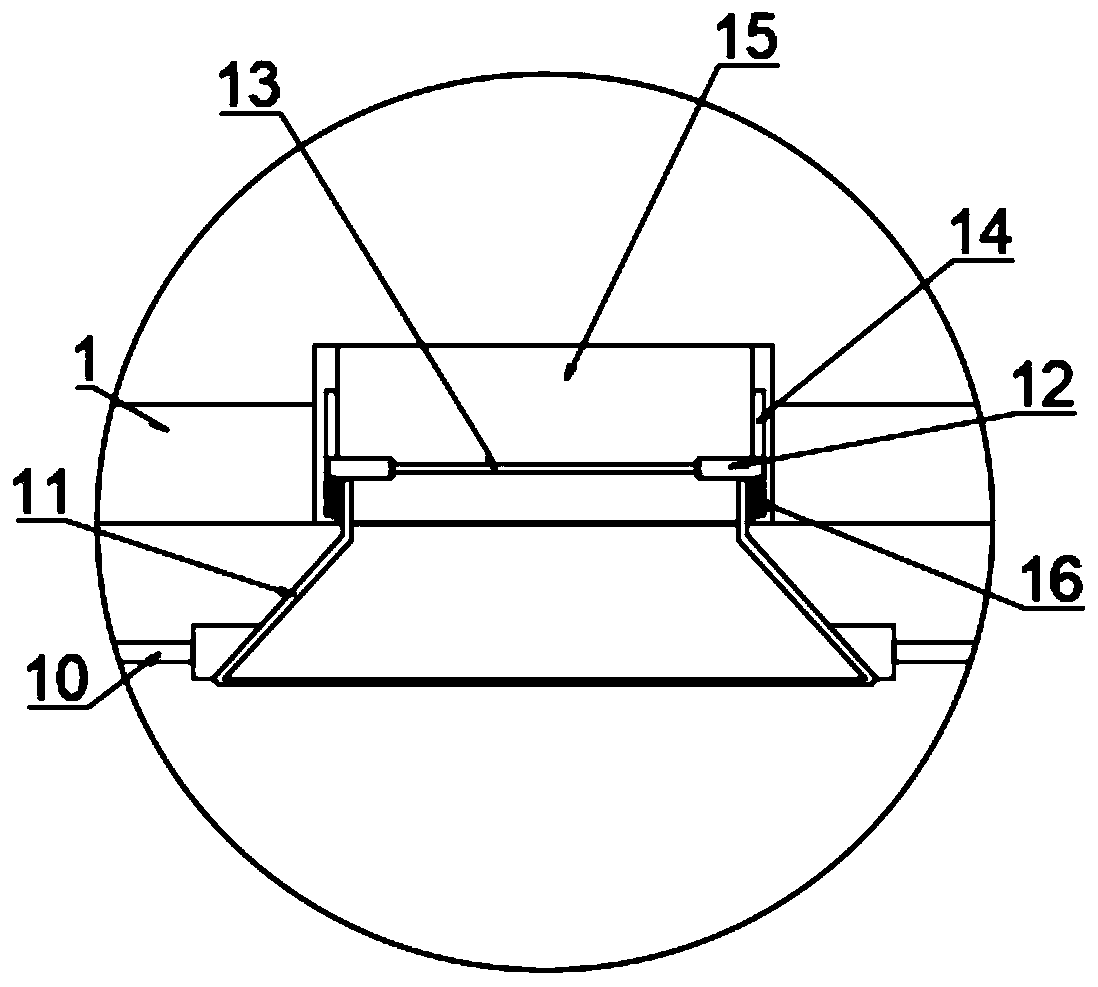
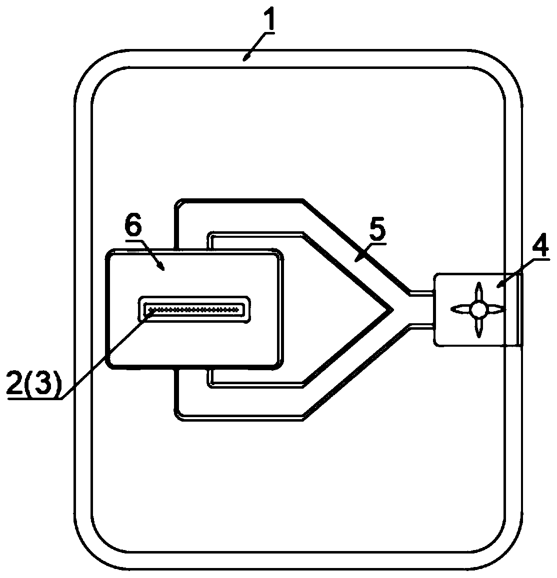
[0030] refer to Figure 1-3 , a powerful yarn clearer for a textile machine, comprising a body 1, the middle part of both sides of the body 1 is connected with a feed pipe 2 and a discharge pipe 3, the feed pipe 2 and the discharge pipe 3 are extended into the body 1, stretched straight A row of yarns enters from the feed pipe 2 and passes through from the discharge pipe 3.

[0031] In the machine body 1, the outer peripheral sides of the feeding pipe 2 and the discharging pipe 3 are equipped with a bellows 6, one side of the bellows 6 is fixedly connected to the inner wall of the body 1, and the upper and lower ends are connected with the same connecting pipe 5, and the connecting pipe 5 is Y-shaped. , two Y-shaped tops are connected to the two ends of the ventilation box 6 and the bottom one is connected to the output end of the fan 4, so that the wind output by the fan 4 to the bellows 6 is evenly distributed in the bellows 6.

[0032] The end of the connecting pipe 5 away...

Embodiment 2

[0046] refer to Figure 4-6 , compared with the first embodiment, the connecting rod 10 is replaced by a first connecting rod 201 , a second connecting rod 202 , and a third connecting rod 203 .

[0047] One end of the first connecting rod 201 is fixedly connected to the air outlet plate 11, the middle part is rotatably connected to the support rod 204 and the other end is rotatably connected to the second connecting rod 202, and the middle part of the second connecting rod 202 is rotatably connected to the support rod 204 and is away from the first connecting rod 202 One end of a connecting rod 201 is provided with a chute 2021 in the axial direction, and the two sides of the chute 2021 are connected with a third connecting rod 203 through a rotating shaft;

[0048] The middle part of the third connecting rod 203 is provided with two spacer rings 18 in a clearance fit, and both sides of the two spacer rings 18 are fixedly connected with the same straight rod 19. The auxiliary ...

Embodiment 3

[0053] refer to Figure 7 , Compared with Embodiments 1 and 2, an exhaust fan 21 is installed at the two air outlets 15 on the body 1 .

[0054] Now the principle of embodiment three of the present invention is described as follows:

[0055] An exhaust fan 21 is installed at the two air outlets 15 on the body 1, which is conducive to improving the flow velocity of the gas in the body 1, thereby accelerating the discharge of the gas mixed with impurities after cleaning;

[0056] At the same time, when the opposing winds meet and disperse into the body 1, the scattered airflow is converged and guided to avoid redundant flow in the body 1 and affect the cleaning effect of the subsequent opposing winds.


PUM


Abstract

The invention discloses a strong yarn cleaner of a textile machine, and relates to the technical field of textile machinery. The strong yarn cleaner comprises a machine body, wherein the middle partsof the two sides of the machine body are provided with a feeding pipe and a discharging pipe; the feeding pipe and the discharging pipe extend into the machine body; the outer peripheral sides of thefeeding pipe and the discharging pipe in the machine body are in clearance fit with air boxes respectively; one sides of the air boxes are fixedly connected to the inner side wall of the machine body,and the upper end and the lower end of the air box communicate with the same communicating pipe; one end, away from the corresponding air box, of each communicating pipe communicates with the outputend of a fan; and the fans are fixedly connected to the inner side wall of the machine body. When the strong yarn cleaner is adopted for cleaning a row of yarns, convection air is output to the surfaces of the yarns through two groups of fans, the communicating pipes, the air boxes and feeding pipes; and in the blowing process of convection air, bidirectional blowing and cleaning is carried out onthe surfaces of the yarns, and a higher cleaning effect is achieved compared with one-way air cleaning.

Description

technical field [0001] The invention relates to the technical field of textile machinery, in particular to a powerful yarn clearer for a textile machine. Background technique [0002] The basic raw material of the textile machine is the textile yarn, and the quality of the textile yarn directly affects the quality of the textile. However, after the textile yarn is processed, hairiness and silk flocks are often attached to the whole body. If it is directly put into textile use, it will not only affect the quality of the textile, but also affect the textile process. Therefore, the hairiness and silk wadding on the yarn need to be cleaned before the yarn is put into weaving. [0003] At present, the cleaning air is generally drawn to the surface of the yarn by means of an exhaust device to clean it. There are two cleaning methods, one is to blow the yarn vertically, and the other is to blow along the direction of the yarn. Both methods have their own advantages. inferior: ...

Claims


Application Information

Patent Timeline
Patent Type & Authority Applications(China)
IPC IPC(8): D02J7/00
CPCD02J7/00
Inventor 李彦军
Owner HEFEI C&P NONWOVEN PROD
Learn More