Integrated steel structure shaft with lift halls and construction process thereof

A technology for steel structures and elevator halls, applied in vertical pipelines, building components, building structures, etc., can solve the problems of increasing the space occupied by building roads with elevators, affecting the effective space of roads, and greatly affecting residents, so as to ensure Effective traffic space, high construction efficiency, and reduced construction period

Pending Publication Date: 2020-03-27
北京亟光电梯科技有限公司
View PDF1 Cites 1 Cited by
  • Summary
  • Abstract
  • Description
  • Claims
  • Application Information

AI Technical Summary

Problems solved by technology

[0005] 1. Since the above-mentioned steel structure shaft is composed of 4 columns, its self-stability is poor, and it needs to be connected with the original building to ensure its own stability. At present, the steel structure shaft is generally connected by a corridor, and the corridor It can also be used as a waiting hall between the elevator and the original building. However, when installing the corridor, scaffolding needs to be erected. The construction is cumbersome and the construction period is long. Impact on the stability of the original building
[0006] 2. For steel structure elevators of this type of structure, the waiting hall is generally set between the steel structure shaft and the original building, with a length of 1.5-3m, which increases the space occupied by the original building road for the installation of the elevator. Compared with For old buildings, it seriously affects the effective space of the road

Method used


Image

  • Integrated steel structure shaft with lift halls and construction process thereof
  • Integrated steel structure shaft with lift halls and construction process thereof
  • Integrated steel structure shaft with lift halls and construction process thereof

Examples


Embodiment 1

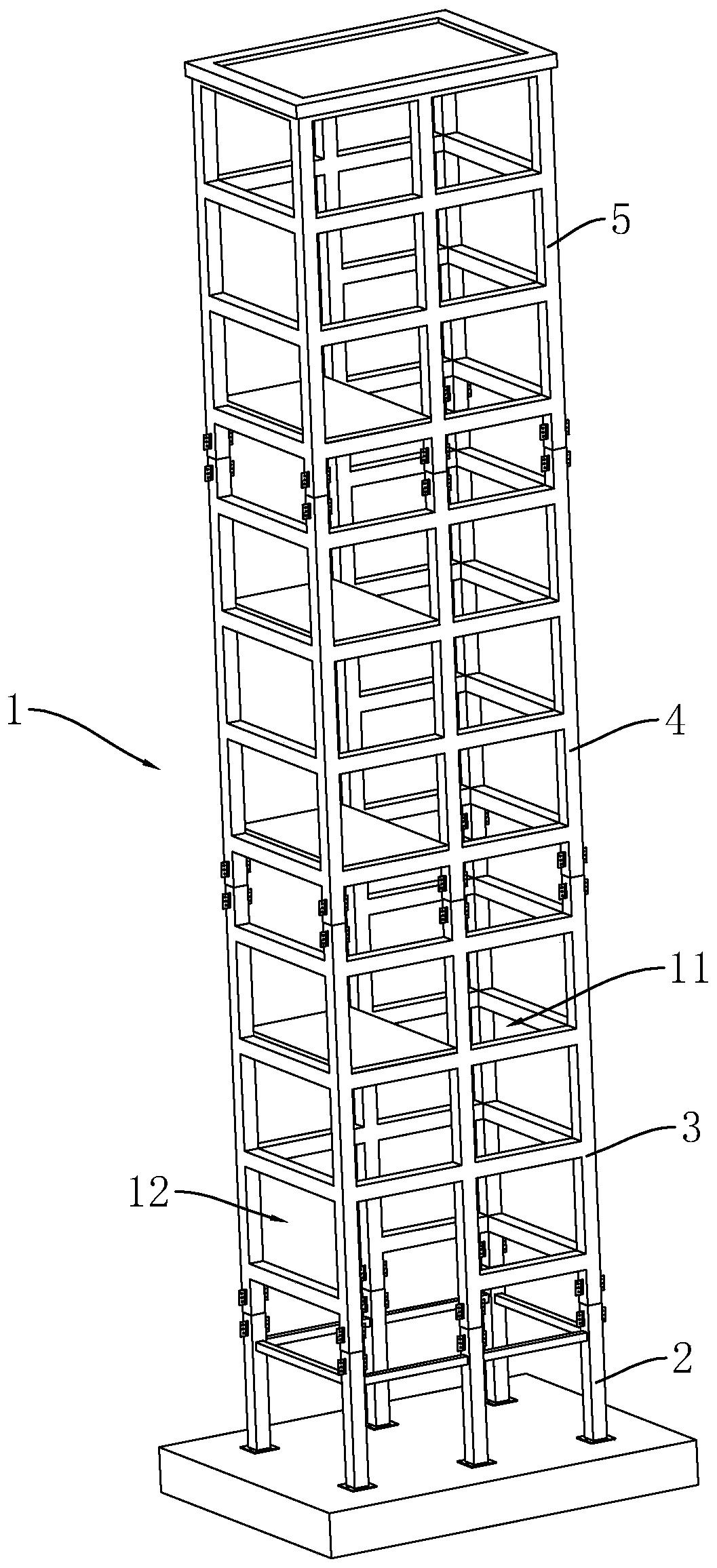
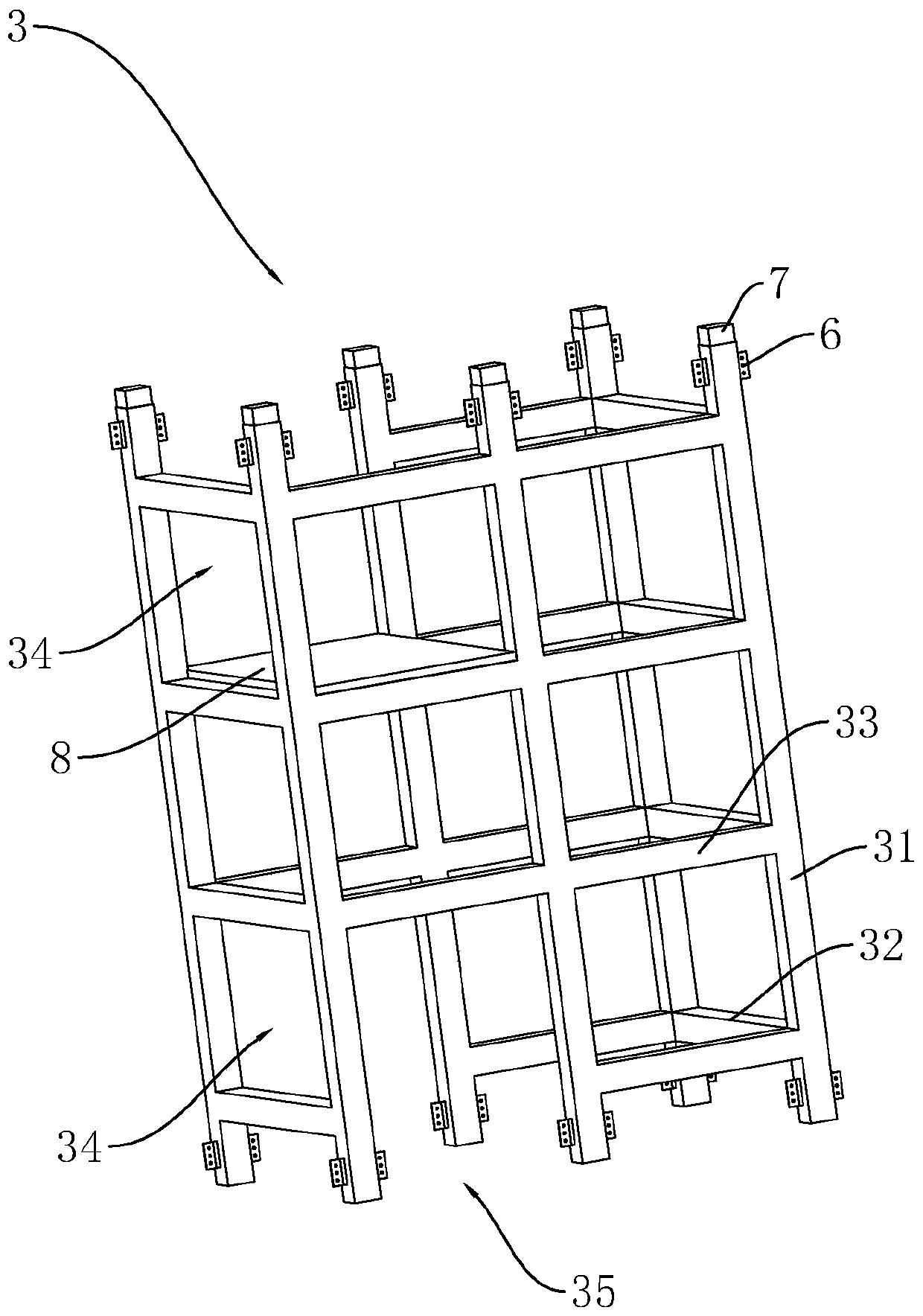
[0041] refer to figure 1 , is an integrated steel structure hoistway with a waiting hall disclosed in the present invention, including a steel structure hoistway 1, and the steel structure hoistway 1 includes a basic frame 2, a bottom module 3, a multi-section standard module 4, The top module 5 and the roof 51 , the base frame 2 , the bottom module 3 , the standard module 4 and the top module 5 are welded and fixed by the socket sleeve 7 , and the roof 51 is fixed on the upper end of the top module 5 . The bottom module 3 , the standard module 4 and the top module 5 are respectively covered with an enclosure structure, which can be glass, aluminum plate, thermal insulation integrated board, etc.

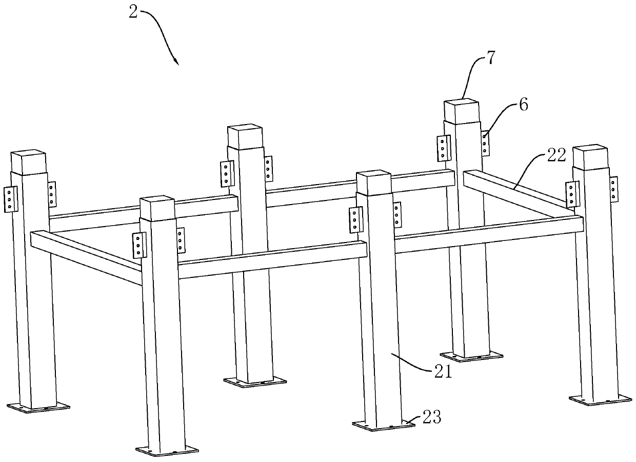
[0042] refer to figure 2 , the basic frame 2 includes six square columns 21, and the six square columns 21 are arranged in a rectangle, and a square beam 22 is welded at the upper end of the square column 21 between adjacent square columns 21, and a square steel plate 23 is welded o...

Embodiment 2

[0049] A construction process for an integrated steel structure hoistway with a waiting hall, comprising the following steps:


PUM


Abstract

The invention relates to an integrated steel structure shaft with lift halls for an elevator added to the exterior of an existing building. The integrated steel structure shaft comprises a steel structure shaft body. The steel structure shaft body comprises a bottom layer module, multiple sections of standard modules and a top layer module. The bottom layer module, the standard modules and the toplayer module are fixedly connected with one another. Each unit module comprises six stand columns which are arrayed in a rectangular shape and beams which are fixedly arranged between every two adjacent stand columns and at the upper ends and the lower ends of the stand columns correspondingly, wherein at least one group of reinforcing beams are arranged between the middles of every two adjacentstand columns, a rectangular first shaft body for placing an elevator is formed among four adjacent stand columns, and a second shaft body for arranging the corresponding lift hall is formed between the first shaft body and the other two stand columns. The integrated steel structure shaft has the advantages of carrying the lift halls and being independent of the existing building, high in stability, assembly rate and construction efficiency.

Description

technical field [0001] The invention relates to the technical field of modular elevator installation in the field of existing building renovation, in particular to an integrated steel structure hoistway with a waiting hall and its construction technology. Background technique [0002] In recent years, with the continuous improvement of the living standards of urban residents, people have higher and higher requirements for the living environment, and they are more pursuing a comfortable living environment and convenient transportation. In particular, our country has entered the stage of population aging. For the elderly residents living in high-rise buildings, installing elevators is one of the important manifestations of improving their living conditions. The traditional way to add elevators to existing residences is to use brick-concrete structures, concrete structures and steel structures constructed on site as elevator shafts. After the civil works are completed, the elev...

Claims


Application Information

Patent Timeline
Patent Type & Authority Applications(China)
IPC IPC(8): E04F17/00E04B1/24
CPCE04B1/24E04B1/2403E04F17/005
Inventor 陈艳彬史学磊陈艳华
Owner 北京亟光电梯科技有限公司
Why Eureka
Try Eureka