
Active regeneration grading control method for particle trap

A particle trap and active regeneration technology, which is applied in the direction of machines/engines, engine components, combustion engines, etc., to achieve the effect of reducing exhaust back pressure and timely and effectively removing carbon deposits

Active Publication Date: 2020-03-27
DONGFENG MOTOR CORP HUBEI
View PDF24 Cites 25 Cited by
  • Summary
  • Abstract
  • Description
  • Claims
  • Application Information

AI Technical Summary

Problems solved by technology

[0005] CN108757116A discloses "An Actively Regenerated Particle Trap and Its Control Method", which uses a heat transfer medium to transfer heat to the filter body of the particle trap, and solves the problem of uniform heating in the regeneration process of the particle trap through an electric heating device. question
The above two active regeneration control methods are not realized by changing the engine parameters

Method used


Image

  • Active regeneration grading control method for particle trap
  • Active regeneration grading control method for particle trap

Examples


Embodiment Construction

[0029] The following specific implementation methods are used to explain the technical solutions of the claims of the present invention, so that those skilled in the art can understand the claims. The protection scope of the present invention is not limited to the following specific implementation structures. The protection scope of the present invention includes the technical solution of the claims of the present invention made by those skilled in the art and is different from the following specific embodiments.

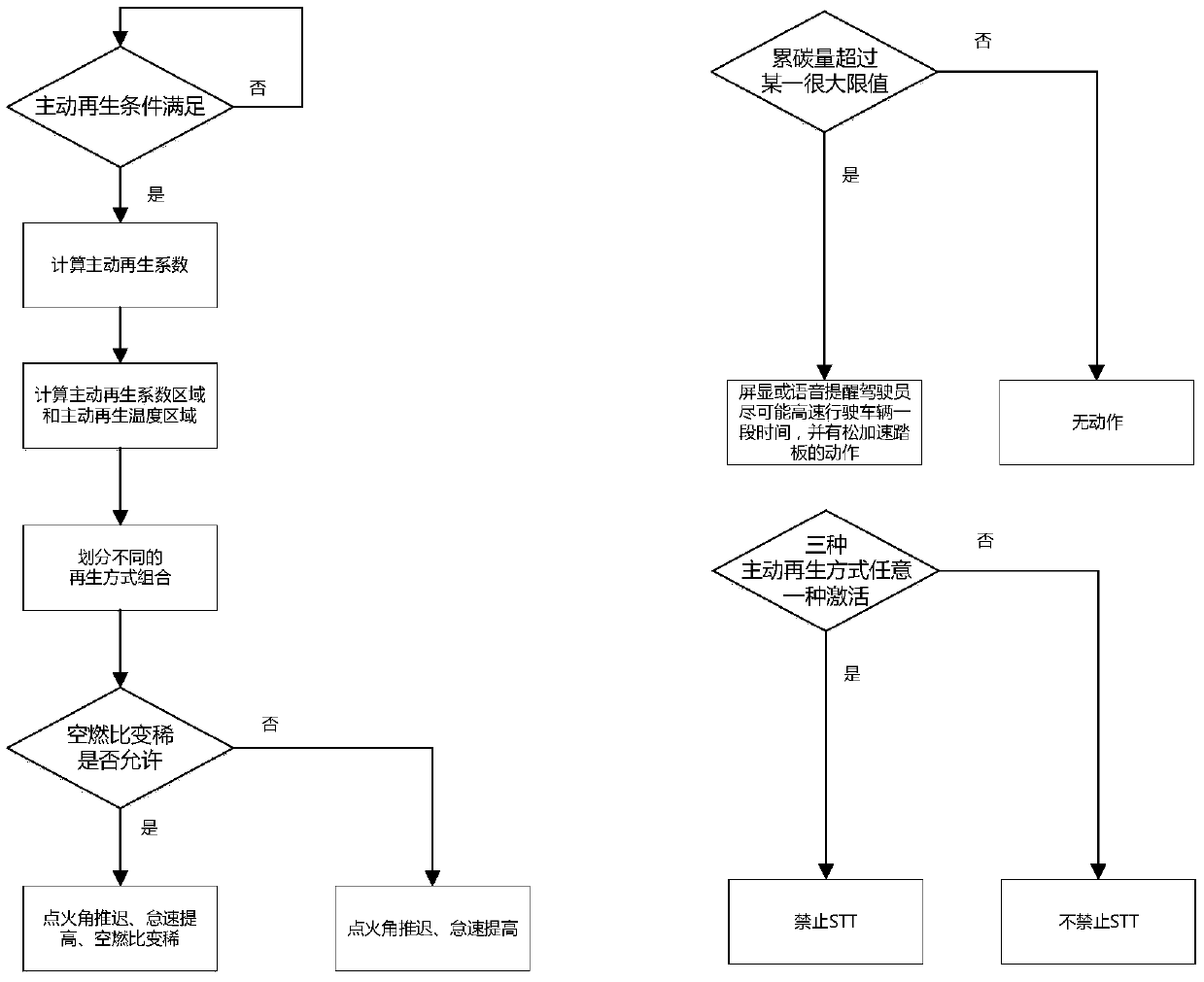
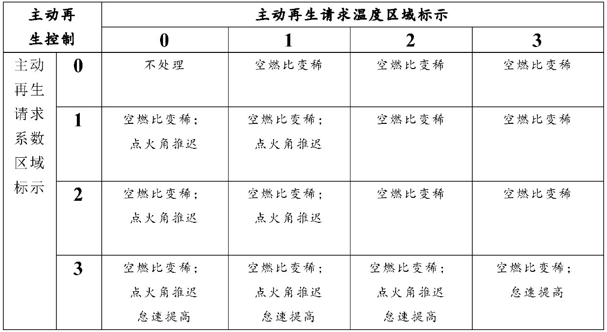
[0030] In the process of active regeneration, when the engine running state refers to the normal operation of the engine, retarding the ignition angle is to delay the normal ignition angle. For example, when the active regeneration request coefficient area is marked as 3 and the active regeneration request temperature area is marked as 0, the Reducing the ignition efficiency is 0.9 times of normal ignition efficiency; air-fuel ratio becomes leaner is to increase the...


PUM


Abstract

The invention discloses an active regeneration grading control method for a particle trap. The active regeneration grading control method aims to acquire the real-time carbon loading amount and temperatures of the particle trap. According to the carbon loading amount, a plurality of carbon loading limit values are determined, a plurality of temperature limit values are determined according to thetemperatures, the real-time carbon loading amount and the carbon loading amount limit values of the particle trap are compared, the real-time particle trap temperatures and the temperature limit values are compared, an active regeneration mode is determined, and the active regeneration mode is one or a combination containing more than one of the conditions that an engine is controlled to defer theignition angle, the air-fuel ratio becomes lean, and the idle speed is increased. According to the active regeneration grading control method for the particle trap, the mode of active regeneration isdetermined according to the regions where different carbon loading amount and the temperatures of the particle trap are located and the marking of the region, so that the carbon deposition is effectively removed in time when the carbon loading amount is too high, and the exhaust back pressure is reduced.

Description

technical field [0001] The invention belongs to the motor vehicle emission control technology, in particular to a particle trap regeneration technology, in particular to a particle trap active regeneration control technology. Background technique [0002] In order to improve the environmental requirements of exhaust emissions, particle traps have been widely used in motor vehicles. Particle traps can capture more than 90% of the number of particles in car exhaust. However, the captured particles will adhere to the filter body of the filter. As the particles continue to accumulate, the exhaust resistance of the engine will continue to increase. When the particle filter is severely blocked, the back pressure of the engine exhaust system will increase. The engine power and economy will also deteriorate. In order to solve this problem, the regeneration technology of particle filter came into being. [0003] Existing regeneration techniques for particle traps include passive r...

Claims


Application Information

Patent Timeline
IPC IPC(8): F01N9/00
CPCF01N9/002F01N2900/1606Y02T10/40
Inventor 秦龙杨柳春叶婷陈龙田丰民
Owner DONGFENG MOTOR CORP HUBEI
Learn More