
Pneumatic pressing machine for electric engineering

A technology of electric power engineering and crimping machine, which is applied in the field of electric power and can solve problems such as component jamming, inability to slide, and mechanical defects

Active Publication Date: 2020-03-27
HEBI POWER SUPPLY OF HENAN ELECTRIC POWERCORP
View PDF7 Cites 0 Cited by
  • Summary
  • Abstract
  • Description
  • Claims
  • Application Information

AI Technical Summary

Problems solved by technology

[0002] The crimping machine is widely used in power engineering operations. It can press the metal head to the wire end, and then conduct it. The terminal is usually for more convenient connection. It can stably connect the two wires together without soldering. , and you only need to unplug it when disassembling. The conventional pneumatic crimping machines on the market are divided into three operating modes: fully automatic, semi-automatic and manual. The only difference is whether it has the peeling function and the feeding function, but apart from the difference in function, the pneumatic crimping machine has a unified mechanical defect problem, that is, the long-term operation will consume the lubricating grease inside the equipment, causing its mechanical action to be slow, and even cause the components to get stuck. It cannot slide and be damaged. Based on the above premise, this case developed a pneumatic crimping machine for power engineering to solve this problem.

Method used


Image

  • Pneumatic pressing machine for electric engineering
  • Pneumatic pressing machine for electric engineering
  • Pneumatic pressing machine for electric engineering

Examples


Embodiment

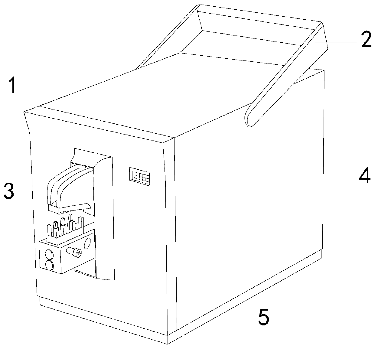
[0020] see figure 1 , the present invention provides a pneumatic crimping machine for electric power engineering. Its structure includes: a main body 1, a handle 2, a molding mechanism 3, a counter 4, and a bottom plate 5. Connected, the die mechanism 3 is arranged on the front side of the main body 1 and is connected to the inside. The main body 1 is provided with a counter 4 and a bottom plate 5 is installed at the bottom of the main body 1. The driving components together form a complete main structure, and the inside of the main body is driven by a motor plus a frequency converter. This structure has no mechanical failures of traditional clutches, can simplify internal mechanical parts, reduce wear and replacement of mechanical parts, and has high torque and low vibration. , high stability, which helps to improve the ultra-quiet working performance. The handle 2 is used to lift the equipment so that it has the function of application in different places and portable movem...


PUM


Abstract

The invention discloses a pneumatic pressing machine for electric engineering. The machine comprises a main machine body, a lifting handle, a mold pressing mechanism, a counter and a base plate; the top positions of the two sides of the main machine body are connected with the lifting handle; and the mold pressing mechanism is arranged in the front surface direction of the main machine body, and is connected with the internal thereof. The machine has the beneficial effects that an extrusion pulley in a butter pushing device performs inflation and energy storage in the structure by dint of thestretching characteristic of an energy storage bag column and enables the structure to operate, so that the stability of the butter pushing speed can be guaranteed, the quicker overflowing of butter is prevented, an effect similar to stirring can be achieved on the butter, the blockage in pipes caused by solidification of the butter due to the temperature is prevented, and the equipment internal can be effectively lubricated to prevent blunt mechanical actions.

Description

technical field [0001] The invention relates to the field of electric power, in particular to a pneumatic crimping machine for electric power engineering. Background technique [0002] The crimping machine is widely used in power engineering operations. It can press the metal head to the wire end, and then conduct it. The terminal is usually for more convenient connection. It can stably connect the two wires together without soldering. , and you only need to unplug it when disassembling. The conventional pneumatic crimping machines on the market are divided into three operating modes: fully automatic, semi-automatic and manual. The only difference is whether it has the peeling function and the feeding function, but apart from the difference in function, the pneumatic crimping machine has a unified mechanical defect problem, that is, the long-term operation will consume the lubricating grease inside the equipment, causing its mechanical action to be slow, and even cause the c...

Claims


Application Information

Patent Timeline
IPC IPC(8): F16N11/08F16N39/00H01R43/048H01R43/05
CPCF16N11/08F16N39/00H01R43/048H01R43/0488H01R43/05
Inventor 温丽虹
Owner HEBI POWER SUPPLY OF HENAN ELECTRIC POWERCORP
Learn More