Swing type drying oven device for tea drying

A swing type, oven technology, applied in tea drying, drying, dryer and other directions, can solve the problems of poor tea drying effect, single drying structure, low efficiency, etc., to improve drying and dust filtering effect, good Stirring effect, good dustproof effect

Inactive Publication Date: 2020-03-27
含山县官塘石壁茶厂
View PDF5 Cites 2 Cited by
  • Summary
  • Abstract
  • Description
  • Claims
  • Application Information

AI Technical Summary

Problems solved by technology

[0003] The existing tea drying device has a single traditional drying structure, which has poor drying effect and low efficiency on tea

Method used


Image

  • Swing type drying oven device for tea drying
  • Swing type drying oven device for tea drying
  • Swing type drying oven device for tea drying

Examples


Embodiment 1

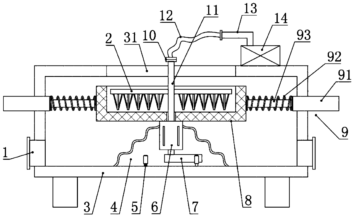
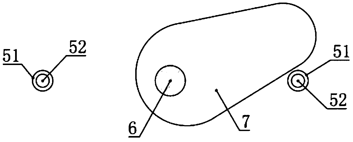
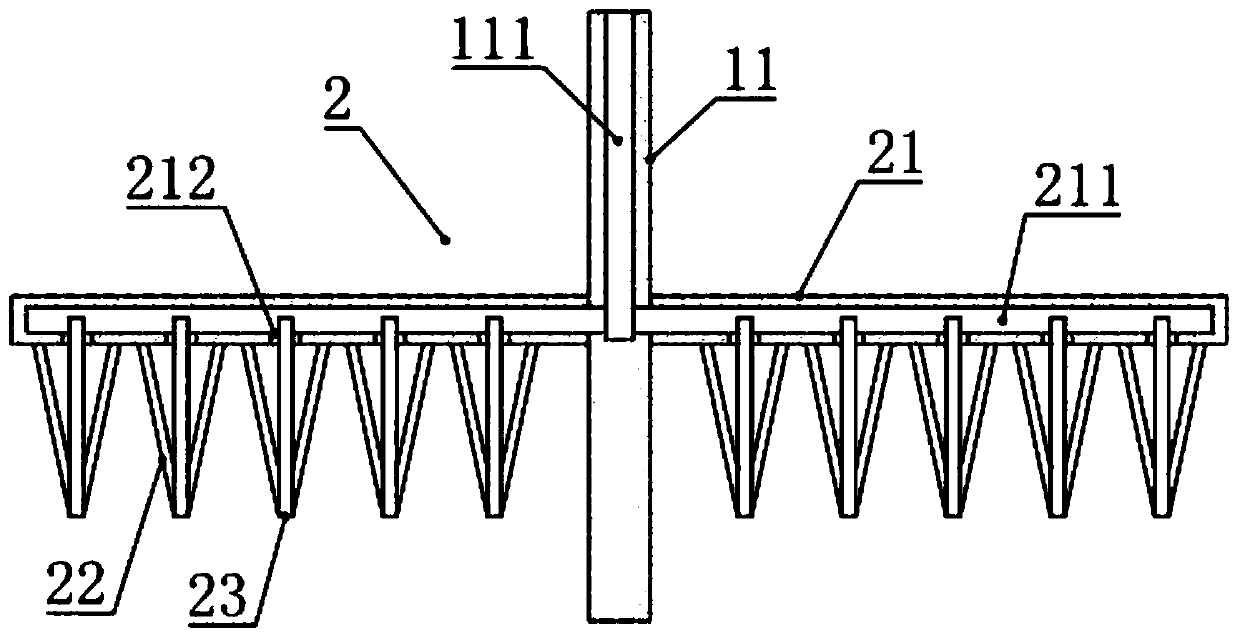
[0026] see figure 1 , in an embodiment of the present invention, a swing-type oven device for drying tea leaves, comprising a box body 3, the inner side of the box body 3 is provided with a loading net box 8 with an upper opening, and the left and right sides of the box body 3 An elastic telescopic assembly 9 is respectively installed and fixed on the wall, and the inner end of the elastic telescopic assembly 9 is connected and fixed with the loading net box 8, and the elastic telescopic assembly 9 can stably support the loading net box 8 and facilitate the loading net The left and right movement of the box 8; the bottom of the loading net box 8 is fixed with a biaxial extension motor 6, and a cam 7 is installed and fixed on the lower output shaft of the biaxial extension motor 6, and the left and right sides of the bottom of the box 3 The side is correspondingly provided with a toggle assembly 5 that can be linked with the cam 7; the upper output shaft of the biaxial extensio...

Embodiment 2

[0028] see Figure 1-4 , the difference between this embodiment and embodiment 1 is:

[0029] In this example, if figure 1 As shown, the top of the box body 3 is provided with an inlet and outlet 31 compatible with the loading cage 8, and the inlet and outlet 31 are used for picking and placing tea leaves in the loading cage 8.

[0030] In this example, if figure 1 As shown, the elastic telescopic assembly 9 includes a mounting cylinder 91, a spring 92 and a telescopic rod 93, the mounting cylinder 91 is fixed on the side wall of the box body 3, and the mounting cylinder 91 is provided with a telescopic rod 93 for cooperation and sliding. The inner end of telescopic rod 93 is fixed on the loading net box 8, and also is provided with spring 92 on the telescopic rod 93 between described installation tube 91 and loading net cage 8, can be loaded with material net cage 8 by spring 92. Elastic support is beneficial to return to the original position after the material-carrying c...


PUM


Abstract

The invention relates to the technical field of tea machining, in particular to a swing type drying oven device for tea drying. The swing type drying oven device comprises a box body, wherein a material carrying net cage is arranged on the inner side of the box body, elastic stretchable assemblies are mounted and fixed on the left and right side walls of the box body respectively, and the inner ends of the elastic stretchable assemblies are fixedly connected with the material carrying net cage, a double-shaft extension motor is mounted and fixed at the bottom of the material carrying net cage,cams are mounted and fixed on a lower side output shaft of the double-shaft extension motor, and toggle assemblies capable of being linked with the cams are correspondingly arranged on the left sideand the right side of the bottom of the box body; an upper side output shaft of the double-shaft extension motor is fixedly connected with a rotating shaft, the rotating shaft inside the material carrying net cage is circumferentially provided with stirring assemblies, the upper end of the rotating shaft is connected with a connecting hose through a rotating connecting piece, the other end of theconnecting hose is connected with an air exhaust pipe, and the other end of the air exhaust pipe is connected with a temperature control fan arranged at the top of the box body. The swing type dryingoven device is novel and reasonable in structure, good in drying effect on tea leaves and high in popularization and application value.

Description

technical field [0001] The invention relates to the technical field of tea processing, in particular to a swing oven device for drying tea. Background technique [0002] Tea is people's daily drink, which is beneficial to people's health. In the process of making tea, a drying process is required, and drying equipment is used in the drying of tea. [0003] The existing tea drying device has a single traditional drying structure, which has poor drying effect and low efficiency on tea leaves. Therefore, in view of the above present situation, there is an urgent need to develop a swing oven device for tea drying to overcome the deficiencies in current practical applications. Contents of the invention [0004] The purpose of the embodiments of the present invention is to provide a swing oven device for drying tea leaves, so as to solve the problems raised in the above-mentioned background technology. [0005] In order to achieve the above purpose, embodiments of the present ...

Claims


Application Information

Patent Timeline
Patent Type & Authority Applications(China)
IPC IPC(8): F26B11/20F26B25/18F26B25/04F26B21/00A23F3/06
CPCA23F3/06F26B11/20F26B21/004F26B25/04F26B25/18F26B2200/20
Inventor 裴善银
Owner 含山县官塘石壁茶厂
Why Eureka
Try Eureka