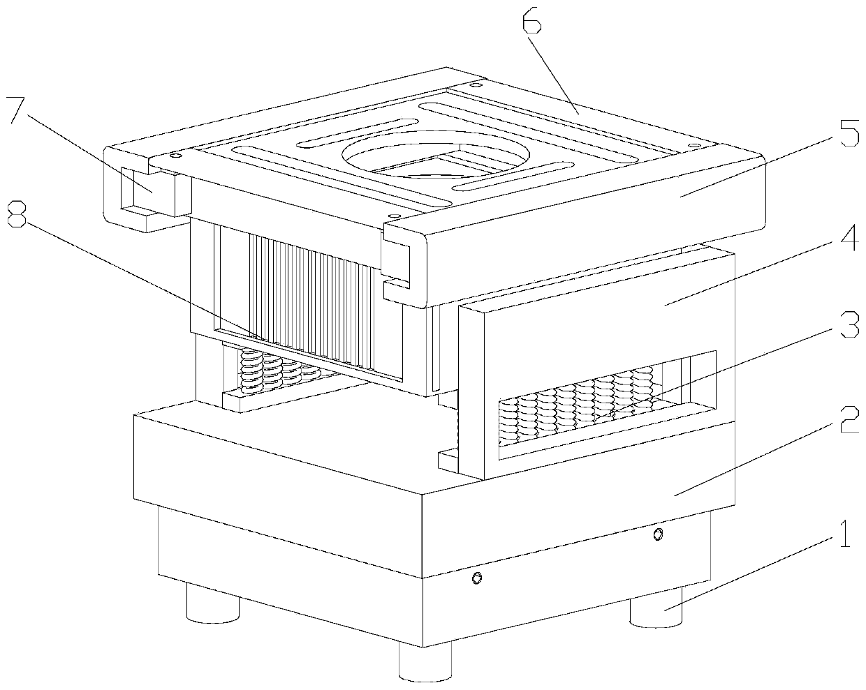
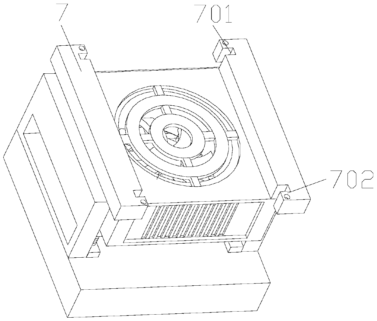
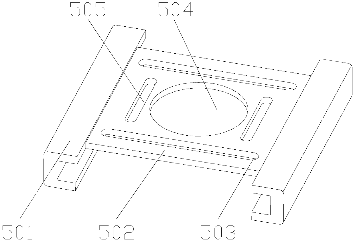
Supporting base of power device box
A power equipment box and support base technology, which is applied to seismic equipment, electrical components, substation/distribution device casings, etc., can solve the problems that the installation base does not have a leveling device, which affects the normal operation of the power equipment and the temperature of the power equipment box is high. , to achieve the effect of improving maintenance efficiency, reducing impact and reducing losses
- Summary
- Abstract
- Description
- Claims
- Application Information
AI Technical Summary
Problems solved by technology
Method used
Image

Examples
Embodiment Construction
[0041] Attached below Figure 1-16 , clearly and completely describe the technical solutions in the embodiments of the present invention, obviously, the described embodiments are only some of the embodiments of the present invention, not all of them. Based on the embodiments of the present invention, all other embodiments obtained by persons of ordinary skill in the art without making creative efforts belong to the protection scope of the present invention.
[0042] In describing the present invention, it should be understood that the terms "longitudinal", "transverse", "upper", "lower", "front", "rear", "left", "right", "vertical", The orientations or positional relationships indicated by "horizontal", "top", "bottom", "inner", "outer", etc. are based on the orientations or positional relationships shown in the drawings, and are only for the convenience of describing the present invention, rather than indicating or It should not be construed as limiting the invention by impl...
PUM
 Abstract
Description
Claims
Application Information