Polishing device for welding tip

A technology of grinding device and welding tip, applied in positioning device, grinding machine, grinding/polishing equipment, etc., can solve the problems of requiring movement and time-consuming, and achieve the effect of simple grinding operation

Active Publication Date: 2020-03-31
TOYOTA JIDOSHA KK
View PDF5 Cites 2 Cited by
  • Summary
  • Abstract
  • Description
  • Claims
  • Application Information

AI Technical Summary

Problems solved by technology

However, in this method, an operator's action is required, and man-hours are required
Therefore, there is room for simplification in such cases as well

Method used


Image

  • Polishing device for welding tip
  • Polishing device for welding tip
  • Polishing device for welding tip

Examples


Embodiment approach 1

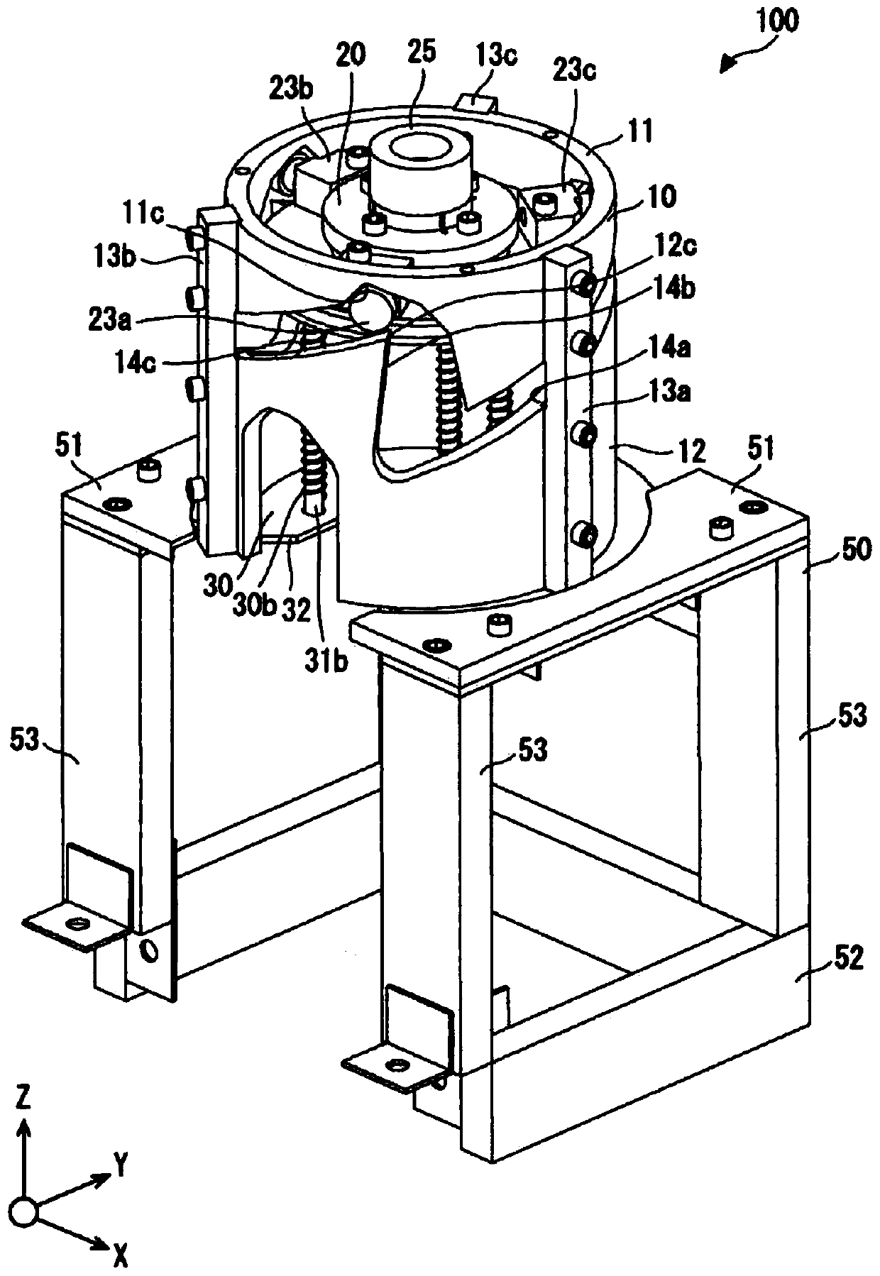
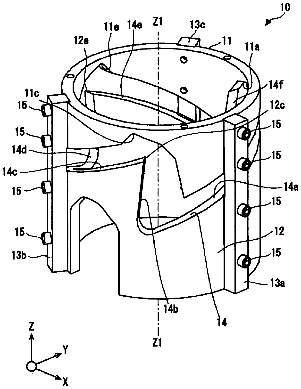
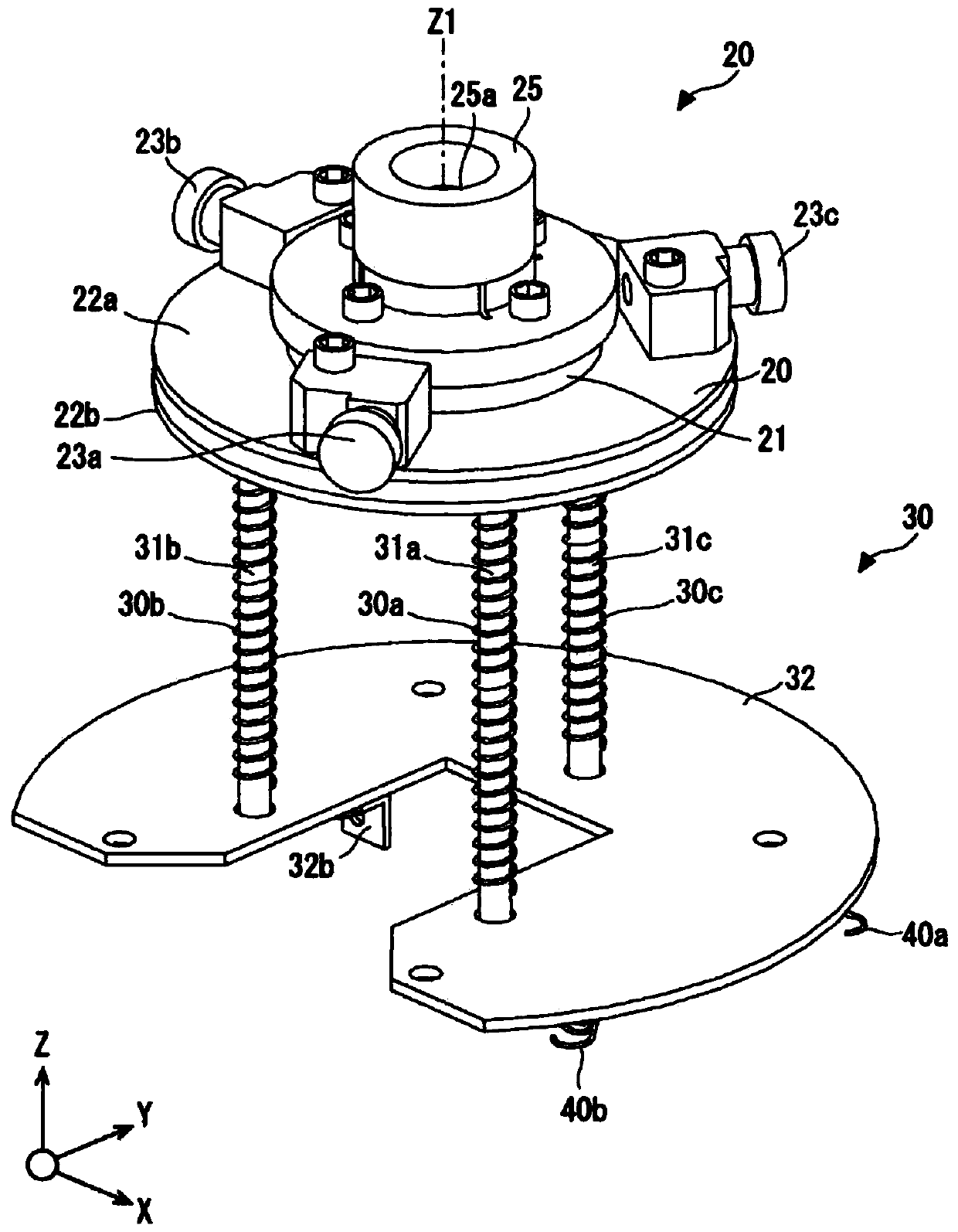
[0034] (Embodiment 1) Refer to Figure 1 to Figure 6 Embodiment 1 will be described. It should be noted that, of course, figure 1 and the right-handed xyz coordinates shown in the other drawings are coordinates for the convenience of describing the positional relationship of the constituent elements. Usually, the positive direction of the z-axis is vertically upward, and the xy plane is a horizontal plane, which are common among drawings. figure 1 It is a perspective view which shows the grinding|polishing apparatus of Embodiment 1. figure 2 It is a perspective view which shows the holder of the grinding|polishing apparatus of Embodiment 1. image 3 It is a perspective view which shows the grinding|polishing part etc. of the grinding|polishing apparatus of Embodiment 1. Figure 4 It is a plan view showing the polishing unit and the like of the polishing device according to the first embodiment. Figure 5 It is the perspective view which looked at the polishing apparatus ...


PUM


Abstract

A polishing device for a welding tip includes a cylindrical holder; and a polishing unit. The polishing unit includes a blade configured to polish a welding tip. The blade polishes the welding tip dueto rotation of the polishing unit. The holder includes a groove extending along an entire inner circumference of the holder. The groove includes axial groove portions each of which extends along an axis of the holder, and inclined groove portions each of which extends for a specified first distance and is inclined in one direction with respect to the axial groove portions. The axial groove portions and the inclined groove portions are alternately arranged. The polishing unit includes projected portions each of which extends to an inside of the groove, and the number of the projected portionsis two or more and is equal to or less than the number of the axial groove portions.

Description

technical field [0001] The invention relates to a grinding device for a welding tip. Background technique [0002] There is a tip grinding device that grinds a tip by rotating either one of the tip and the cutter in contact with each other. An example of such a grinding device is disclosed in Japanese Patent Laid-Open No. 07-144285. [0003] The inventors of the present application found the following problems with regard to such a tip polishing device. In grinding devices for welding tips, in addition to actuators for translational movement of the welding tips, actuators for rotating the welding tips or cutters are often required. Therefore, there is room for cost cutting. [0004] On the other hand, a method of grinding the tip by rotating the tip or the cutter with the operator's hand is also conceivable. However, this method requires an operator's action and takes man-hours. Therefore, there is room for simplification in such a case as well. Contents of the invent...

Claims


Application Information

Patent Timeline
Patent Type & Authority Applications(China)
IPC IPC(8): B23P23/04B23Q3/06
CPCB23P23/04B23Q3/062B23K11/3063B23K11/3054B23B5/166B24B19/16
Inventor 岩野吉宏金久保辽三田尚吾
Owner TOYOTA JIDOSHA KK
Why Eureka
Try Eureka