
Water-vapor mixing system of super pressing and suction combined pumping system and working method thereof

A water-vapor mixing and super technology, applied in the direction of pressure pumps, infrastructure engineering, machines/engines, etc., can solve problems such as increased equipment costs, high labor costs, and water column height restrictions, and achieve the effects of saving equipment costs and speeding up efficiency

Pending Publication Date: 2020-03-31
SHANGHAI CHANGKAI GEOTECHN ENG
View PDF0 Cites 6 Cited by
  • Summary
  • Abstract
  • Description
  • Claims
  • Application Information

AI Technical Summary

Problems solved by technology

[0002] The traditional deep foundation pit dewatering uses vacuum pump equipment to discharge the air in the suction pipe and then uses the pressure difference between the inside and outside of the pipe to press the water out of the well. Under the limit state, the vacuum pump can pump up to about 9.8 meters of water column, and the height of the extracted water column is limited limit
Since the upward reaction force of the rising water column comes from the pressure difference between the inner and outer water columns of the pumping pipe, the upward reaction force of this technology becomes smaller and smaller as the depth of the well point increases, and the pumping becomes more and more difficult. When the limit of the vacuum pump is reached, There may even be a situation where the water is stopped, and the technical limitations are very obvious
Moreover, this technology requires a lot of equipment in the early stage, and the labor cost is high. Moreover, as the depth of the well point increases, the requirements for equipment are getting higher and higher, resulting in an increase in equipment costs.

Method used


Image

  • Water-vapor mixing system of super pressing and suction combined pumping system and working method thereof
  • Water-vapor mixing system of super pressing and suction combined pumping system and working method thereof

Examples


Embodiment

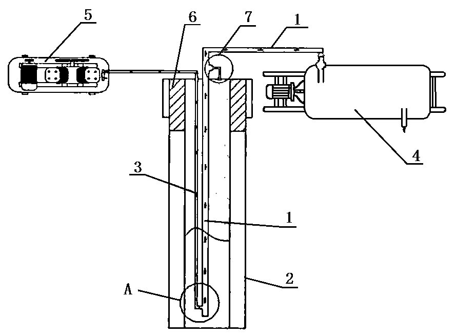
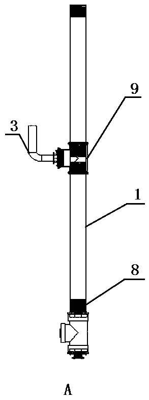
[0018] Example: such as figure 1 , 2 As shown, the present embodiment specifically relates to a water-steam mixing system of a super pressure-suction combined pumping system and its working method. The water-steam mixing system includes a pumping device and an air supply device arranged on the dewatering well 2, wherein:

[0019] The pumping device mainly includes a water outlet pipe 1, a vacuum pump 4, and a vacuum application device 7. The vacuum pump 4 is arranged at the entrance ground of the dewatering well 2. One end of the water outlet pipe 1 is connected with the vacuum pump 4, and the other end runs through the sealed well cover at the wellhead of the dewatering well 2. 6 and extend vertically to the bottom of the dewatering well 2. In addition, the vacuum applying device 7 is specifically a pipe body. One end of the vacuum applying device 7 runs through the sealed manhole cover 6 and communicates with the upper part of the dewatering well 2, and the other end communi...


PUM


Abstract

The invention discloses a water-vapor mixing system of a super pressing and suction combined pumping system and a working method thereof. The water-vapor mixing system includes a pumping device and anair supply device, the pumping device includes a water outlet pipe and a vacuum pump, one end of the water outlet pipe communicates to the vacuum pump, the other end of the water outlet pipe penetrates through a sealed manhole cover on a precipitation well to reach the bottom of the precipitation well, the air supply device includes an air supply pipe and an air compressor, one end of the air supply pipe is in communication with the air compressor, and the other end of the air supply pipe penetrates through the sealed manhole cover on the precipitation well to reach the bottom of the precipitation well and communicates with the lower portion of the water outlet pipe. According to the water-vapor mixing system, air is pressed in through the air compressor, a water column in the water outlet pipe bears upward rising force, a water-vapor mixture is formed to reduce the specific gravity of the rising water column in the water outlet pipe, and the purpose of rapid pumping is achieved. Thewater-vapor mixing system has the advantages that the water-vapor mixing system greatly breaks through the height limit of the water column pumped by the vacuum pump, pressing and suction are combinedto speed up the pumping efficiency, and the equipment cost is saved.

Description

technical field [0001] The invention relates to the technical field of deep well pumping, in particular to a water vapor mixing system of a super pressure-suction combined pumping system and a working method thereof. Background technique [0002] The traditional deep foundation pit dewatering uses vacuum pump equipment to discharge the air in the suction pipe and then uses the pressure difference between the inside and outside of the pipe to press the water out of the well. Under the limit state, the vacuum pump can pump up to about 9.8 meters of water column, and the height of the extracted water column is limited limit. Since the upward reaction force of the rising water column comes from the pressure difference between the inner and outer water columns of the pumping pipe, the upward reaction force of this technology becomes smaller and smaller as the depth of the well point increases, and the pumping becomes more and more difficult. When the limit of the vacuum pump is r...

Claims


Application Information

Patent Timeline
IPC IPC(8): E02D19/10F04F1/02
CPCE02D19/10F04F1/02
Inventor 殷立锋王彭宇代江张航
Owner SHANGHAI CHANGKAI GEOTECHN ENG
Learn More