
Intermittent forward and reverse barring gear driven by hydraulic cylinder

A cranking device, intermittent technology, applied in the direction of transmission device, fluid transmission device, belt/chain/gear, etc., can solve the problem of axial thermal expansion sensitivity, only one-way automatic cranking, and cannot provide more accurate cranking Angle and other problems, to achieve the effect of precise control of rotation angle and precise turning angle

Pending Publication Date: 2020-03-31
中国船舶重工集团公司第七0三研究所
View PDF0 Cites 0 Cited by
  • Summary
  • Abstract
  • Description
  • Claims
  • Application Information

AI Technical Summary

Problems solved by technology

[0003] In order to solve the problems that the existing cranking device cannot provide a relatively accurate cranking angle in some occasions, is sensitive to axial thermal expansion, and can only automatically crank in one direction, the present invention further proposes an intermittent positive and negative gear driven by a hydraulic cylinder. steering wheel device

Method used


Image

  • Intermittent forward and reverse barring gear driven by hydraulic cylinder
  • Intermittent forward and reverse barring gear driven by hydraulic cylinder
  • Intermittent forward and reverse barring gear driven by hydraulic cylinder

Examples


specific Embodiment approach 1

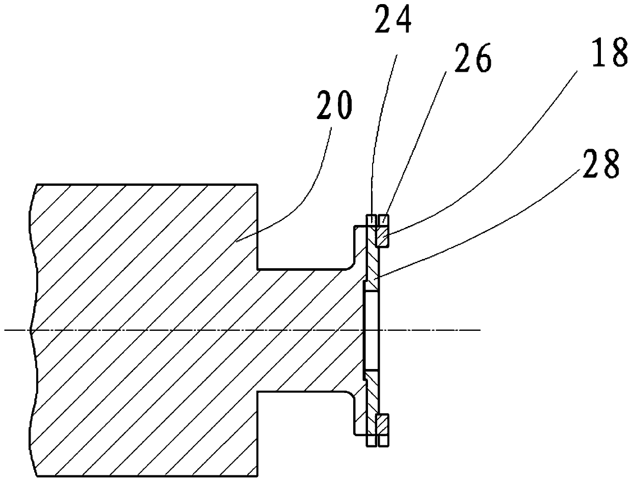
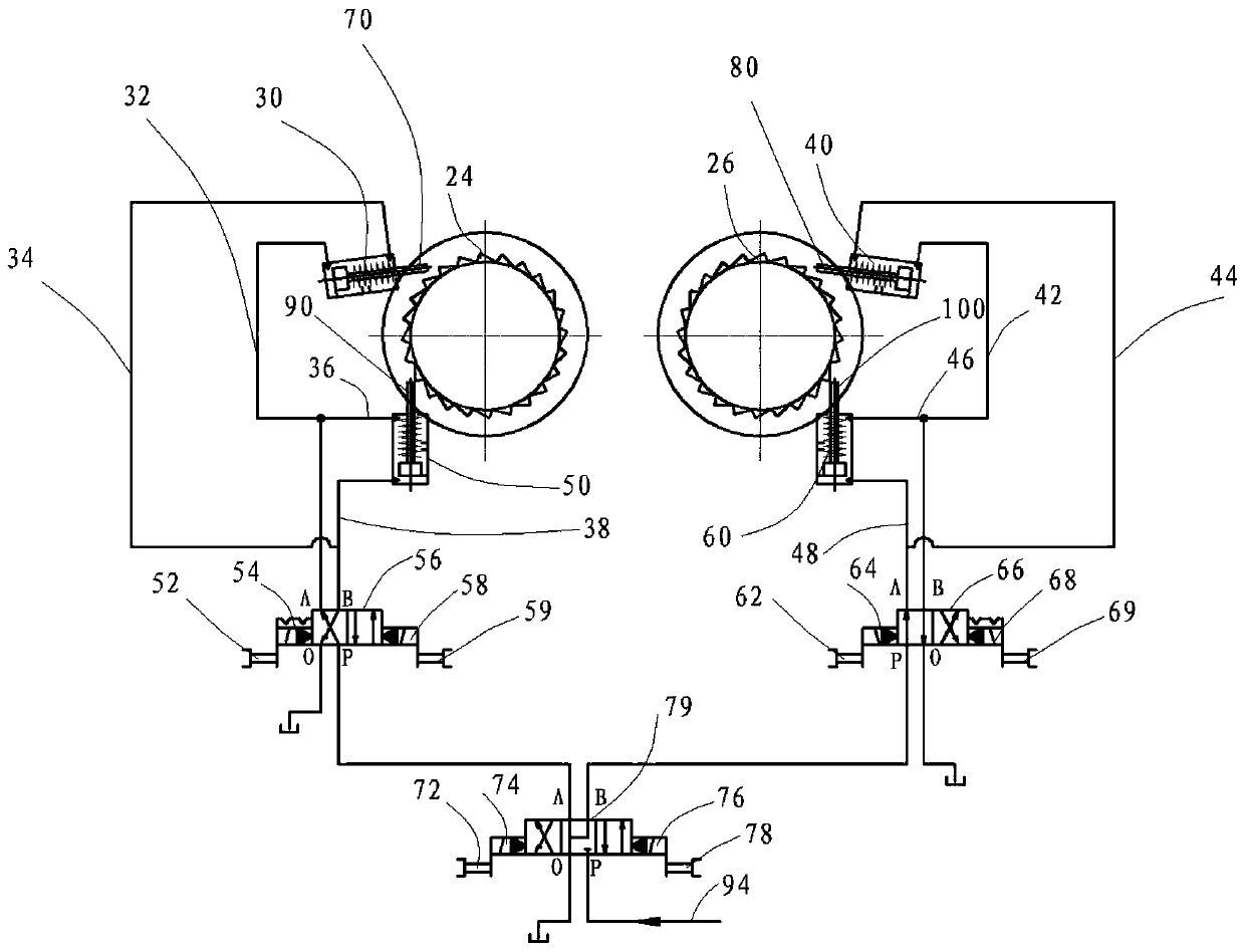
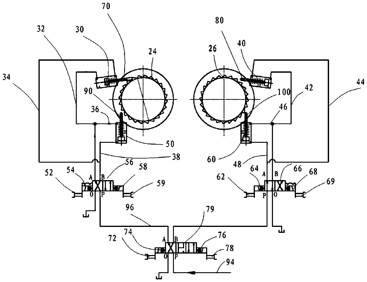
[0014] Specific implementation mode one: combine Figure 1 to Figure 4 Describe this embodiment, a hydraulic cylinder-driven intermittent forward and reverse cranking device described in this embodiment includes a reverse crank gear ring 18, a forward crank gear ring 28, a forward crank oil cylinder I30, a reverse gear Barring cylinder I40, forward cranking cylinder II50, reverse cranking cylinder II60, forward cranking electromagnetic reversing valve 56 and reverse cranking electromagnetic reversing valve 66, forward cranking gear ring 28 and reverse cranking The gear ring 18 is coaxially fixed on the rotor shaft 20, the outer circumferential side wall of the forward gear ring 28 is provided with forward gear teeth 24 along the circumferential direction, and the outer circumferential side of the reverse gear ring 18 The wall is provided with the reverse disc gear 26 along the circumferential direction, the gear tooth working surface inclination direction of the forward disc g...

specific Embodiment approach 2

[0016] Specific implementation mode two: combination Figure 1 to Figure 2 This embodiment will be described. The forward gear ring 28 and the reverse gear ring 18 in this embodiment are fixedly connected to the rotor shaft 20 through a plurality of connecting bolts respectively. Other compositions and connection methods are the same as those in Embodiment 1.

specific Embodiment approach 3

[0017] Specific implementation mode three: combination Figure 1 to Figure 2 To illustrate this embodiment, the forward cranking cylinder piston rod I70 of the forward cranking cylinder I30 and the forward cranking cylinder piston rod II90 of the forward cranking cylinder II50 in this embodiment act on the forward cranking cylinder respectively when extending out. On the gear tooth working surface of tooth 24, the reverse crank cylinder piston rod I80 of the reverse crank cylinder I40 and the reverse crank cylinder piston rod II100 of the reverse crank cylinder II60 respectively act on the reverse crank The tooth face of tooth 26. Other compositions and connection methods are the same as those in the second embodiment.


PUM


Abstract

The invention discloses an intermittent forward and reverse barring gear driven by a hydraulic cylinder, relates to a barring gear, and solves problems that a barring gear cannot provide a more accurate barring angle in some occasions, is sensitive to axial thermal expansion and can only perform unidirectional automatic barring. The device comprises a reverse barring gear ring, a forward barring gear ring, a forward barring oil cylinder I, a reverse barring oil cylinder I, a forward barring oil cylinder II, a reverse barring oil cylinder II, a forward barring electromagnetic reversing valve and a reverse barring electromagnetic reversing valve, the forward turning gear ring and the reverse turning gear ring are coaxially and fixedly connected to a rotor shaft, the forward barring oil cylinder I and the forward barring oil cylinder II are arranged on the outer side of the forward barring gear ring in the radial direction, the forward barring oil cylinder I and the forward barring oil cylinder II are connected with the forward barring electromagnetic reversing valve, and the reverse barring oil cylinder I and the reverse barring oil cylinder II are arranged on the outer side of the reverse barring gear ring in the radial direction. The device is used for barring.

Description

technical field [0001] The invention relates to a cranking device, in particular to an intermittent forward and reverse cranking device driven by a hydraulic cylinder. Background technique [0002] For units with large resistance torque and large moment of inertia, the rotor needs to rotate at a fixed angle during installation and inspection. In order to facilitate installation, sometimes it needs to rotate intermittently in forward and reverse directions. The traditional barring device generally uses a motor-driven gear reduction device to realize the continuous operation of the barring. After the barring motor stops, the rotor continues to rotate due to inertia, and the angle of the rotor rotation cannot be controlled accurately, which is not conducive to installation and maintenance. In order to have a compact structure, the axial gap between the turning pinion and the turning gear on the rotor of the traditional turning device is about 10mm. In some cases, when the axial...

Claims


Application Information

Patent Timeline
IPC IPC(8): F16H47/02F16H29/00
CPCF16H29/00F16H47/02F16H2047/025
Inventor 闫泽王春玲戴维泽曲盛楠魏君波
Owner 中国船舶重工集团公司第七0三研究所
Learn More