New downlight structure

A downlight, a new type of technology, applied in the field of lighting, can solve problems such as unfavorable standardized production efficiency, incompatibility and mutual assembly of products, and lack of unified industry standards, so as to improve production efficiency and market effect, and achieve large-scale production and popularization. The effect of convenient application and appearance design

Active Publication Date: 2022-05-13
Q E SHENZHEN ELECTRONICS TECH
View PDF28 Cites 0 Cited by
  • Summary
  • Abstract
  • Description
  • Claims
  • Application Information

AI Technical Summary

Problems solved by technology

Due to the strangeness of the structure of the LED light source and the flattening of the light-emitting surface, it does not match the structure of the traditional downlight. Even if it is barely equipped, it cannot achieve satisfactory lighting and aesthetic effects.
As a result, there are LED downlights with integrated light sources and lamps on the market. This type of downlight cannot replace the light source because of the integration. If it is broken, it can only be replaced as a whole. Especially in the European and American markets, the labor cost is high, and the replacement cost is even more prominent
In addition, the integrated downlight is not very convenient to replace, and it is easy to damage the decorative surface of the ceiling, causing joint losses
Or reluctantly place the LED light source in the old-fashioned downlight for use. Although the separation of the light source and the lamp can be solved, due to the uneven light source style, size and power, most light sources cannot be used, and a few can be used. Less than neat and beautiful requirements and ideal lighting effects
[0003] Secondly, the current troubles of the LED downlight industry and even the entire LED lighting industry are: product structures and product configurations are varied, there is no unified industry standard, and products of different categories and brands cannot be compatible and mutually equipped, which is not conducive to standardized production and improvement. Production efficiency, but also inconvenience to users
[0004] In addition, the traditional LED integrated downlight light source cannot be placed along the depth of the inner hole of the downlight, which is not conducive to adjusting the illumination range and eliminating glare

Method used


Image

  • New downlight structure
  • New downlight structure
  • New downlight structure

Examples


Embodiment 1

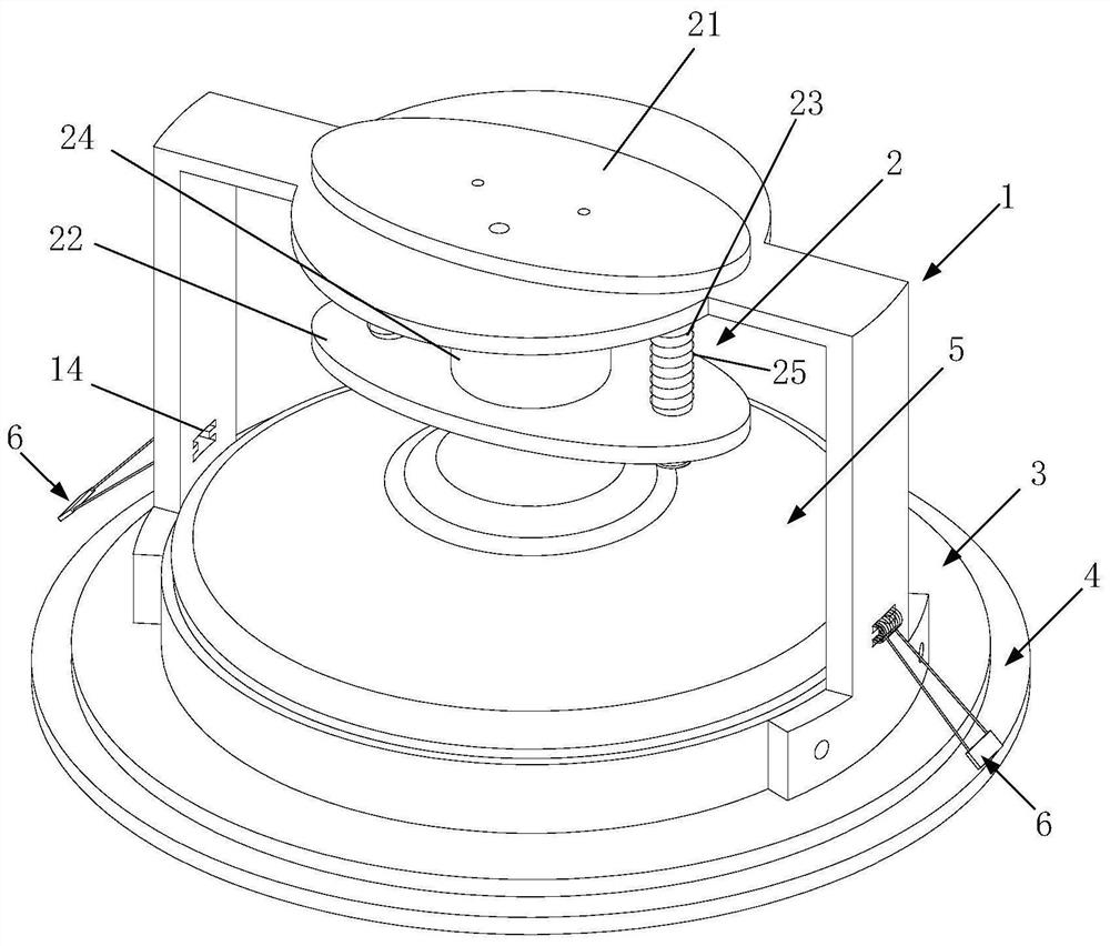
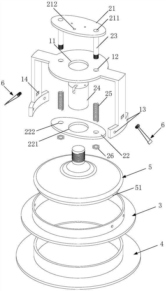
[0053] see figure 1 , figure 2 As shown, a new downlight structure includes a vertical lamp body and a light source 5. The vertical lamp body includes a vertical bracket 1, a movable lamp holder assembly 2, a base 3 and a support ring 4, and the movable lamp holder assembly 2. It is movably connected to the top of the vertical support 1. The base 3 is fixed on the bottom of the vertical support 1 with screws. The support ring 4 is closely combined with the inner wall of the base 3 through a connecting piece; the light source 5 and the movable lamp holder assembly 2 connection, the bottom surface of the light source 5 is provided with a light source boss 51, when the light source 5 is connected to the movable lamp holder assembly 2, the light source boss 51 is just inserted into the inner hole of the support ring 4, limiting the light source 5 in the support ring 4 Horizontal displacement on the ring 4, the light source 5 is supported by the support ring 4 in a static state, ...

Embodiment 2

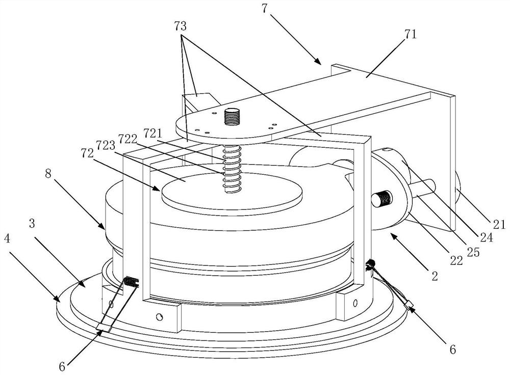
[0059] see image 3 , Figure 4 , Figure 5 As shown, a new downlight structure includes a horizontal lamp body and a horizontally inserted light source 8,

[0060] The horizontal lamp body includes a horizontal bracket assembly 7, a movable lamp base assembly 2, a base 3 and a support ring 4, the movable lamp base assembly 2 is movably connected to the side plate of the horizontal bracket assembly 7, and the base 3 passes through It is fixed on the bottom of the cantilever 73 of the horizontal bracket assembly 7 by riveting, and the support ring 4 is closely combined with the inner wall of the base 3 through a connecting piece; the horizontally inserted light source 8 is connected to the movable lamp holder assembly 2, and the horizontally inserted The light outlet part of the bottom surface of the light source 8 is provided with a horizontal insertion light source boss 81. When the horizontal insertion light source 8 is connected with the movable lamp holder assembly 2, th...

Embodiment 3

[0066] see Figure 6 , Figure 7 As shown, a new downlight structure includes a surface-mounted lamp body and a light source. The surface-mounted lamp body includes a cavity 91, a cavity top cover 92, a movable lamp holder assembly 2 and a support ring 4. The movable The lamp holder assembly 2 is movably connected on the top cover 92 of the cavity, and the top cover 92 of the cavity is installed on the top of the cavity 91 with screws, the bottom of the cavity 91 has a central hole, and the support ring 4 is connected to the cavity The inner wall of the center hole at the bottom of the body 91 is tightly combined through a connecting piece; the light source 5 is connected to the movable lamp holder assembly 2, and the light outlet part of the bottom surface of the light source 5 is provided with a boss 51. When the light source 5 is connected to the movable lamp holder assembly 2, The light source boss 51 is just placed into the inner hole of the support ring 4 to limit the h...


PUM


Abstract

The invention relates to a new type of downlight structure, which includes a lamp body and a light source. The lamp body includes a bracket, a movable lamp holder assembly, a base and a supporting ring. The movable lamp holder assembly is movably connected to the top of the bracket. Installed at the bottom of the bracket, the light source is installed on the movable lamp holder assembly, and moves longitudinally or laterally in the lamp body along with the movable lamp holder assembly. The invention provides a convenient solution for replacing the downlight light source by hand through the ingenious design of the downlight lamp body and the light source structure, and also provides a feasible solution for the standardization of the downlight industry.

Description

technical field [0001] The invention relates to the technical field of lighting, in particular to a novel downlight structure. Background technique [0002] For a long time, in the field of lighting, downlights have been widely used in indoor lighting due to their simplicity, beauty, and many advantages such as being necessary for many lighting places. Due to the strangeness of the structure of the LED light source and the flattening of the light-emitting surface, it does not match the structure of the traditional downlight. Even if it is barely equipped, it cannot achieve satisfactory lighting and aesthetic effects. As a result, there are LED downlights with integrated light sources and lamps on the market. This type of downlight cannot replace the light source because of the integration. If it is broken, it can only be replaced as a whole. Especially in the European and American markets, the labor cost is high, and the replacement cost is even more prominent. Furthermore...

Claims


Application Information

Patent Timeline
Patent Type & Authority Patents(China)
IPC IPC(8): F21S8/02F21V19/02F21V17/10F21Y115/10
CPCF21S8/02F21V19/02F21V17/10F21Y2115/10F21S8/026F21V14/02F21V19/04F21V21/047
Inventor 肖祥柏
Owner Q E SHENZHEN ELECTRONICS TECH
Why Eureka
Try Eureka