A Series-Parallel Composite Pulse Multiplication Circuit Applied to the DC Side of the Rectifier

A technology of multiplication circuit and DC side, which is applied in the field of power electronics, can solve the problems of complex structure of pulse multiplication circuit and poor harmonic suppression ability, and achieve the effect of high reliability, small number of components and low cost

Active Publication Date: 2022-04-19
HARBIN ENG UNIV
View PDF4 Cites 0 Cited by
  • Summary
  • Abstract
  • Description
  • Claims
  • Application Information

AI Technical Summary

Problems solved by technology

[0007] In order to solve the problems of complex structure and poor harmonic suppression ability of the existing pulse wave multiplication circuit, the present invention provides a series-parallel compound pulse wave multiplication circuit applied to the DC side of the rectifier

Method used


Image

  • A Series-Parallel Composite Pulse Multiplication Circuit Applied to the DC Side of the Rectifier
  • A Series-Parallel Composite Pulse Multiplication Circuit Applied to the DC Side of the Rectifier
  • A Series-Parallel Composite Pulse Multiplication Circuit Applied to the DC Side of the Rectifier

Examples


Embodiment 1

[0104] combine figure 1 , Figure 6 , Figure 11 and Figure 16 To illustrate this embodiment, the embodiment described

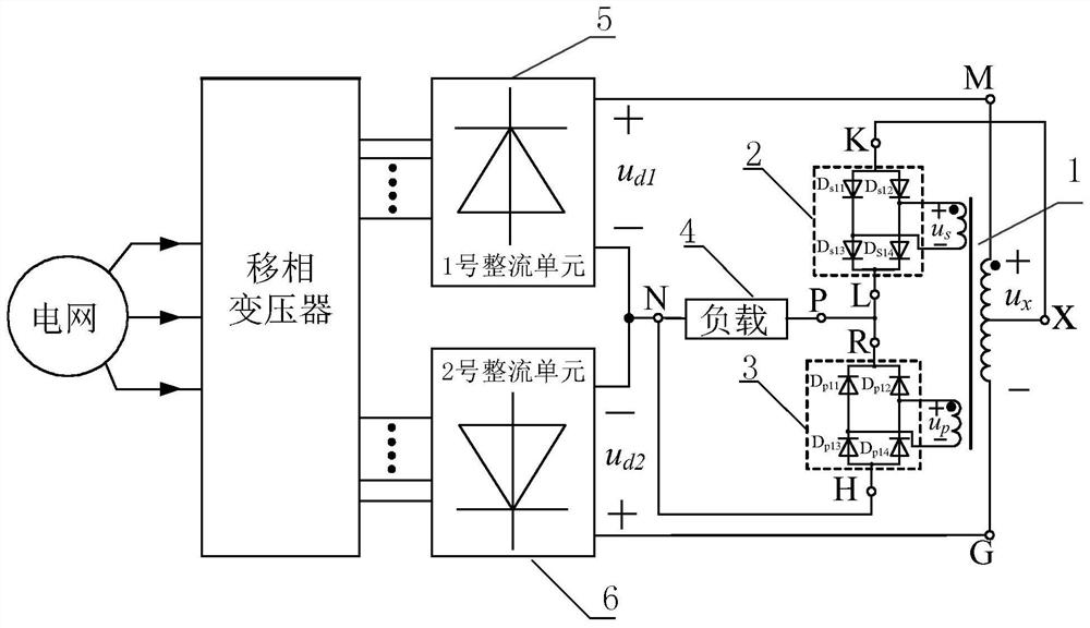
[0105] A series-parallel composite pulse multiplication circuit applied to the DC side of the rectifier,

[0106] Including a balanced reactor 1 with dual secondary windings;

[0107] The primary winding of the balanced reactor 1 with dual secondary windings is used to balance the instantaneous output voltage from the No. 1 rectifier unit 5 and the No. 2 rectifier unit 6, and the balanced electric energy supplies power to the load 4;

[0108] Also included are two single-phase rectifiers for increased pulse count;

[0109] The output end of each secondary winding of the balanced reactor 1 with double secondary windings is respectively connected to the input end of a single-phase rectifier, wherein the output end of one single-phase rectifier is connected in series in the circuit where the load 4 is located, and the other single-phase rectifier The out...

Embodiment 1-1

[0120] see figure 1 To illustrate this embodiment, the preferred embodiment 1-1 of the coordination mode between the balanced reactor 1 with double secondary windings and the single-phase rectifier in this embodiment 1 is:

[0121] When both secondary windings of the balanced reactor 1 with double secondary windings are secondary windings without a center tap, both single-phase rectifiers are single-phase full-bridge rectifiers.

[0122] The present invention only needs to connect a single-phase full-bridge rectifier to the outputs of the two secondary windings of the balanced reactor 1 with double secondary windings respectively, so that the effect of multiplying the pulse number of the rectifier by 3 times can be realized. The circuit has a circuit It has the advantages of simple structure, easy realization, few components and low cost.

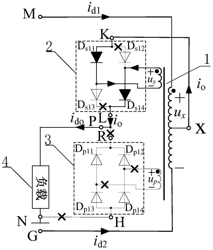
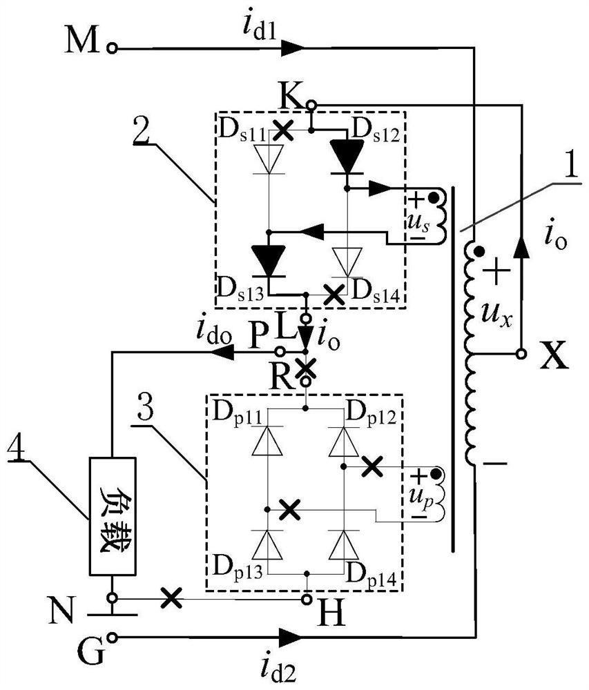
[0123] see figure 1 Illustrate preferred embodiment 1-1, the preferred mode of two single-phase full-bridge rectifiers in preferred embo...

Embodiment 1-2

[0142] see Figure 11 To illustrate this embodiment, the preferred embodiment 1-2 of the coordination mode between the balanced reactor 1 with double secondary windings and the single-phase rectifier in this embodiment 1 is:

[0143] When both secondary windings of the balanced reactor 1 with double secondary windings are secondary windings with a center tap, both single-phase rectifiers are single-phase full-wave rectifiers.

[0144] The present invention only needs to connect a single-phase full-wave rectifier to the outputs of the two secondary windings of the balanced reactor 1 with double secondary windings respectively, so that the effect of multiplying the pulse number of the rectifier by 3 times can be realized. The circuit has a circuit It has the advantages of simple structure, easy realization, few components and low cost.

[0145] see Figure 11 Illustrate preferred embodiment 1-2, the preferred mode of two single-phase full-wave rectifiers in preferred embodimen...


PUM


Abstract

The invention relates to a series-parallel composite pulse multiplication circuit applied to the DC side of a rectifier, belonging to the technical field of power electronics. The invention solves the problems of complex structure and poor harmonic suppression ability of the existing pulse wave doubling circuit. The present invention includes a balanced reactor with double secondary windings and two single-phase rectifiers for increasing the number of pulses; the primary winding of the balanced reactor with double secondary windings is used for rectification from No. 1 rectifier unit and No. 2 rectifier The instantaneous output voltage of the unit is balanced, and the balanced electric energy supplies power to the load; the output terminals of each secondary winding of the balanced reactor with double secondary windings are respectively connected to the input terminal of a single-phase rectifier, and the The output terminal is connected in series in the circuit where the load is located, and the output terminal of the other single-phase rectifier is connected in parallel at both ends of the load. The invention is mainly used for suppressing the harmonics at the grid side.

Description

technical field [0001] The invention belongs to the technical field of power electronics. Background technique [0002] Due to its simple structure, high reliability and low price, the diode rectifier is widely used as the interface circuit between power electronic equipment and the power grid. Compared with other rectification circuits, it is the most simple and reliable rectification circuit. However, the strong nonlinearity of the rectifier device makes it inject a large amount of current harmonics into the grid, causing voltage distortion of the grid and causing serious harmonic pollution to the grid. In order to effectively reduce the input current harmonics, increasing the pulse number of the rectifier is a very effective method in high-power industrial occasions. [0003] At present, there are two main methods to increase the pulse number of the rectifier: one is to multiply the pulse number of the rectifier by phase-shifting multiple connections, which subdivides th...

Claims


Application Information

Patent Timeline
Patent Type & Authority Patents(China)
IPC IPC(8): H02M7/06H02M1/12
CPCH02M7/06H02M1/12H02M1/0038
Inventor 王景芳姚绪梁邓长吉何玉强沈龙赵继成王峰
Owner HARBIN ENG UNIV
Why Eureka
Try Eureka