High-voltage generator for providing high-voltage pulse and high-frequency generator

A high-voltage generator, high-voltage pulse technology, applied in the direction of electric pulse generator circuit, pulse generation, pulse technology, etc., can solve the problems of danger and undesired, and achieve the effect of large pulse width and increased pulse rate

Active Publication Date: 2020-06-19
SIEMENS HEALTHCARE GMBH
View PDF15 Cites 0 Cited by
  • Summary
  • Abstract
  • Description
  • Claims
  • Application Information

AI Technical Summary

Problems solved by technology

This can cause undesired and dangerous states

Method used


Image

  • High-voltage generator for providing high-voltage pulse and high-frequency generator
  • High-voltage generator for providing high-voltage pulse and high-frequency generator
  • High-voltage generator for providing high-voltage pulse and high-frequency generator

Examples


Embodiment Construction

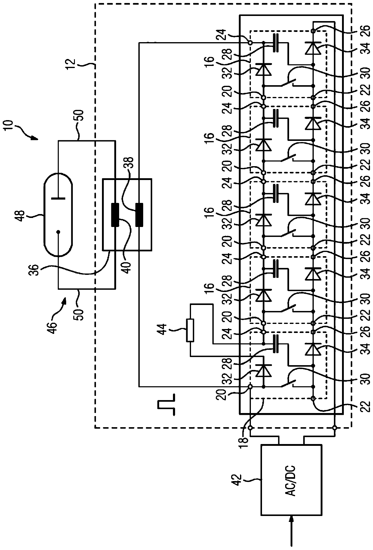
[0049] figure 1 A reduced schematic circuit diagram of a high-frequency generator 10 is shown, which comprises a magnetron 48 which is connected via a line 50 to the high-voltage generator 12 . The high-voltage generator 12 is supplied with electrical energy by a charging unit 42 which is connected for this purpose to a public energy supply network (not shown in further detail) and is supplied with electrical energy therefrom. In the present case, the charging unit 42 is designed to be supplied with a three-phase alternating voltage of approximately 400 V via the public energy supply network. Furthermore, the charging unit 42 is designed to supply a power of approximately 10 kW. The charging unit 42 provides a charging DC voltage of approximately 400V. The magnetron 48 and the electrical line 50 form an electrical circuit 46 .

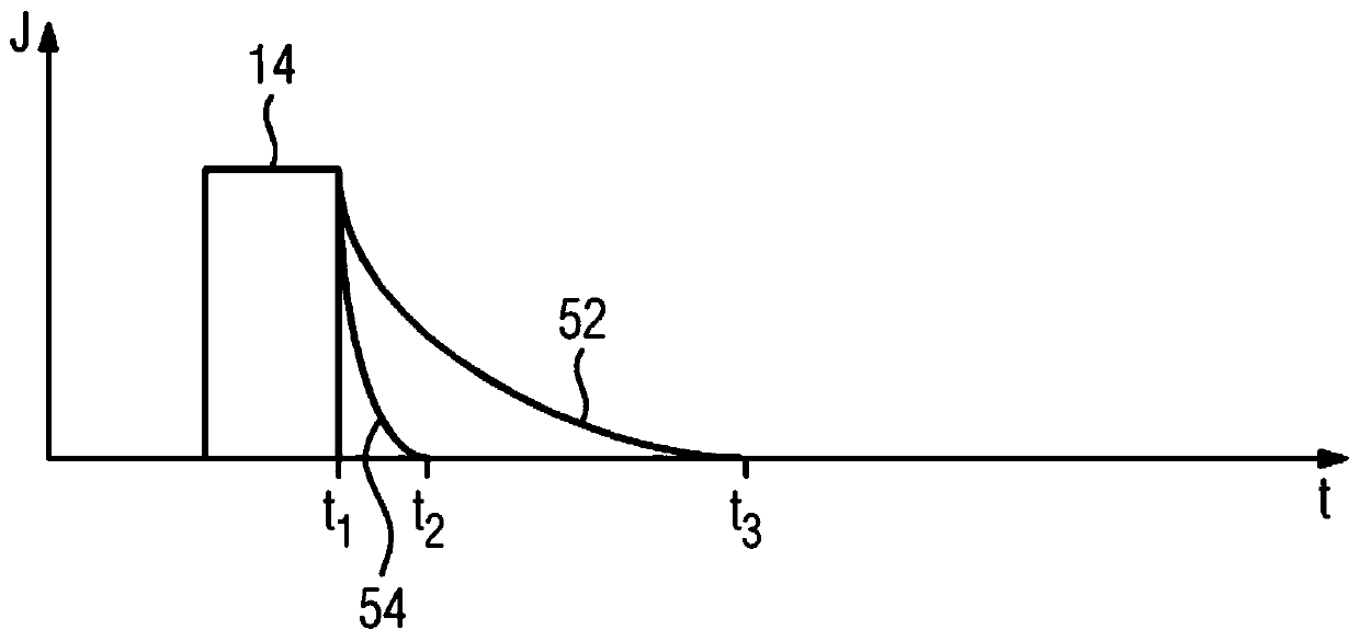
[0050] High voltage generator 12 provides high voltage pulse 14 ( image 3 ), the high-voltage pulse is applied to the magnetron 48, so that the m...


PUM

PropertyMeasurementUnit
electrical resistanceaaaaaaaaaa

Abstract

The invention relates to a high-voltage generator (12) for providing high-voltage pulse (14). The high-voltage generator includes a plurality of energy storage cells (16,18), each including two inputand two output terminals (20,22,24,26) and a capacitor (28). A controllable switching element (30) is connected to the input terminals (20,22) and plus terminals (20,24) and minus terminals (22,26) are electrically connected to one another via a respective diode. The high-voltage generator further includes a series connection comprising the energy storage cells (16,18), a pulse transformer (36), and a charging terminal for charging the capacitors (28). In an embodiment, the high-voltage generator is developed so that a greater pulse rate can be achieved. In an embodiment, at least a respectiveone of the energy storage cells (18) includes an electrical resistance (44), connected in series with the diode connecting the plus terminals (20,24) of the respective energy storage cell (18).

Description

technical field [0001] The invention relates to a high-voltage generator for providing high-voltage pulses, having: a plurality of energy storage units, wherein each of the energy storage units has at least two input terminals and two output terminals and a capacitor, the The capacitor is connected by means of a first of its terminals to the negative of the two input terminals and by means of the second of its terminals to the positive of the two output terminals, wherein a controllable switch is connected to the input terminals element, and the positive and negative terminals are electrically connected to each other via diodes, respectively, in such a way that the corresponding anodes of the diodes are connected to the input terminals, and the corresponding cathodes of the diodes are connected to the output terminals; a series circuit consisting of energy storage cells, wherein the respective input terminals of the respective ones of the energy storage cells are connected to ...

Claims


Application Information

Patent Timeline
Patent Type & Authority Applications(China)
IPC IPC(8): H02M9/04H02M3/07H03K3/53H03K3/017H03K3/023
CPCH02M11/00H02M3/073H03K3/53H03K3/017H03K3/023H02M3/077H01J25/50H01J23/34H03K3/012
Inventor 马文·莫勒斯文·米勒马丁·科施米德尔斯特凡·威林奥利弗·霍伊尔曼
Owner SIEMENS HEALTHCARE GMBH
Why Eureka
Try Eureka