Plasma jet trigger gap test device and test method

A technology for triggering gaps and plasmas, applied to plasmas, electrical components, etc., can solve problems such as huge investment in test circuits and difficulty in implementing high-voltage DC systems, and achieve high equivalence effects

Active Publication Date: 2020-03-31
XI AN JIAOTONG UNIV
View PDF5 Cites 0 Cited by
  • Summary
  • Abstract
  • Description
  • Claims
  • Application Information

AI Technical Summary

Problems solved by technology

[0003] The DC large-capacity test circuit of the plasma jet trigger gap needs to simulate its actual working conditions in the DC system. Since the trigger gap has to withstand high voltage before it is turned on, it is difficult to realize the corresponding high-voltage DC system, and such a test is built. The circuit investment is huge

Method used


Image

  • Plasma jet trigger gap test device and test method
  • Plasma jet trigger gap test device and test method
  • Plasma jet trigger gap test device and test method

Examples


Embodiment Construction

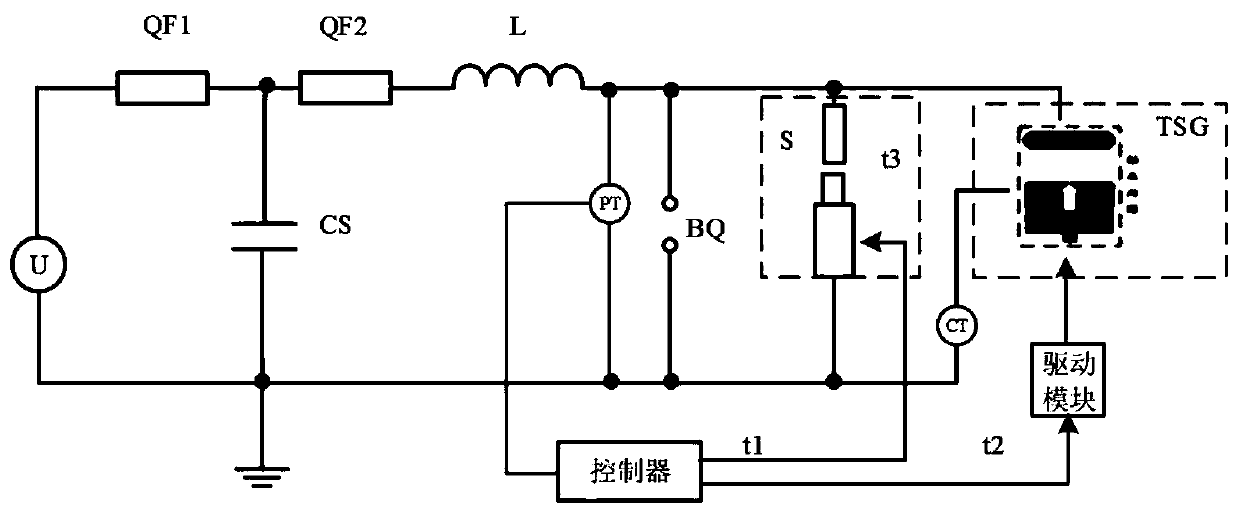
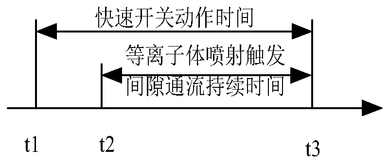
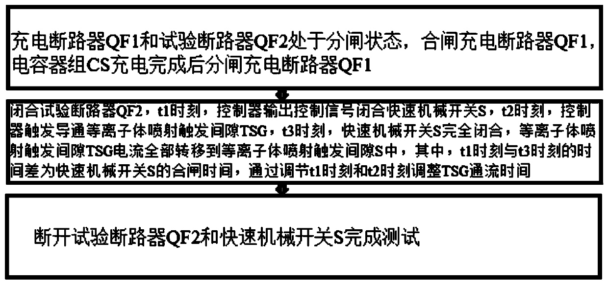
[0037] The following will refer to the attached Figure 1 to Figure 3 Specific examples of the present invention are described in more detail. Although specific embodiments of the invention are shown in the drawings, it should be understood that the invention may be embodied in various forms and is not limited to the embodiments set forth herein. Rather, these embodiments are provided for more thorough understanding of the present invention and to fully convey the scope of the present invention to those skilled in the art.

[0038] It should be noted that certain terms are used in the specification and claims to refer to specific components. Those skilled in the art should understand that they may use different terms to refer to the same component. The specification and claims do not use differences in nouns as a way of distinguishing components, but use differences in functions of components as a criterion for distinguishing. "Includes" or "comprises" mentioned throughout ...


PUM


Abstract

According to the plasma jet trigger gap testing device and method, one end of a charging circuit breaker QF1 is connected with a direct-current power supply, the other end of the charging circuit breaker QF1 is connected with the high-voltage output end of a capacitor bank CS, and the other end of the capacitor bank CS is grounded; one end of the test circuit breaker QF2 is connected with the high-voltage output end of the capacitor bank CS, one end of the reactor L is connected with the test circuit breaker QF2, and the other end is connected with the high-voltage end of the quick mechanicalswitch S; the high-voltage end of the resistance voltage divider PT is connected with the high-voltage end of the plasma jet trigger gap TSG; the other end is connected with the ground, the Rogowski coil CT is sleeved at the low-voltage end of the plasma jet trigger gap TSG; one end of the protection sphere gap BQ is connected with the high-voltage end of the quick mechanical switch S, the other end is connected with the ground, the input end of the controller is connected with a resistance voltage divider PT measurement signal, the first output end of the controller is connected with the driving input end of the driving module, and the second output end is connected with the control end of the quick mechanical switch S.

Description

technical field [0001] The invention relates to the technical field of plasma spraying, in particular to a plasma spraying trigger gap testing device and testing method. Background technique [0002] The plasma jet trigger gap can use pulse discharge to stimulate high-speed plasma jet to penetrate the main gap at an extremely low working coefficient, effectively triggering the switch to be turned on. In the UHV DC transmission project, the plasma jet trigger gap is one of the important equipment to protect the converter station. When the output fault occurs on the AC side, the DC side plasma jet trigger gap and the DC circuit breaker operate at the same time, and the trigger gap is 100μs After about 30ms, the circuit breaker is turned on and the current is transferred to the circuit breaker, which triggers the gap to cut off the arc. In order to verify that the plasma jet trigger gap has a direct current large-capacity flow capacity, a plasma jet trigger gap test device and...

Claims


Application Information

Patent Timeline
Patent Type & Authority Applications(China)
IPC IPC(8): H05H1/00
CPCH05H1/0081
Inventor 李晓昂刘轩东吕玉芳郜淦张明康孙昊晨李杰张乔根
Owner XI AN JIAOTONG UNIV
Why Eureka
Try Eureka