Actuating drive for a motor vehicle

A technology for actuating equipment and motor vehicles, applied in the direction of mechanical equipment, electromechanical devices, electric components, etc., can solve problems such as unsatisfactory technology, achieve the effects of reducing maintenance work, suppressing support noise, and reliable support

Active Publication Date: 2020-03-31
KIEKERT AG
View PDF8 Cites 0 Cited by
  • Summary
  • Abstract
  • Description
  • Claims
  • Application Information

AI Technical Summary

Problems solved by technology

The state of the art is unsatisfactory with regard to the backlash-free support structure of the lead screw

Method used


Image

  • Actuating drive for a motor vehicle
  • Actuating drive for a motor vehicle

Examples


Embodiment Construction

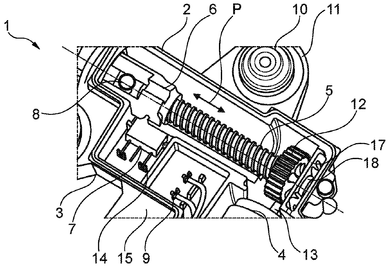
[0032] exist figure 1 The actuating device 1 is shown in a three-dimensional view of the housing box 2 . In order to illustrate the invention clearly, the housing 3 is shown without a housing cover. The actuating device 1 has an electric drive device 4, a lead screw 5, an adjustment member 6, a micro switch 7, a Bowden cable 8, an electrical contact device 9 and an elastic fixing member 10, wherein the elastic fixing member 10 is installed in the casing In the extension 11 of the box 2. The threaded spindle 5 has a worm gear 12 integrally formed on the threaded spindle 5 , wherein the worm wheel cooperates with a worm mounted on the output shaft 13 of the electric drive 4 .

[0033] The worm gear 12 can be driven in both directions of movement by the electric drive 4 , so that the adjusting element 6 and thus the Bowden cable 8 can be adjusted in the direction of the arrow P along the threaded spindle 5 . The movement of the adjusting element 6 can be detected by means of a...


PUM


Abstract

The invention relates to an actuating drive (1) for a motor vehicle, having a housing (3) composed in particular of a housing shell (2) and a housing cover, and an electric drive (4), wherein the drive (4) is used to move an actuating means (6), the actuating means (6) is moved at least by a spindle drive (4, 12, 13) and the spindle (5) can be held under pre-load in a bearing retainer (18). The pre-load can be generated by a spring element (19) that can be inserted into the housing (3).

Description

technical field [0001] The invention relates to an actuating device for a motor vehicle, which has a housing, in particular consisting of a housing box and a housing cover, an electric drive and an adjustment element, wherein the electric drive can By moving the adjusting part, the adjusting part can be moved at least by means of a spindle drive, which can be held in the bearing receptacle under pretension. Background technique [0002] Such an actuating device is preferably used in a motor vehicle in order to carry out an adjusting movement. In this case, the actuating device can be integrated, for example, in the motor vehicle lock or cooperate with the motor vehicle lock. Furthermore, it is also conceivable for the actuating device to move the actuator, for example for closing a fuel tank flap or a storage compartment door. Adjustments are thus used at locations in the vehicle where movement must be initiated or generated. Depending on the field of use and the arrangem...

Claims


Application Information

Patent Timeline
IPC IPC(8): H02K7/116F16H25/20F16C25/08F16H25/24F16H57/039
CPCF16H25/2003F16H25/24F16C27/02F16H57/039H02K7/081H02K7/1166F16C2326/01F16H2025/209H02K2205/03F16H2025/2031F16C2380/27
Inventor C·特普费尔W·施拉布斯T·松嫩沙因
Owner KIEKERT AG
Why Eureka
Try Eureka