Multi-fluid mixer and mixing test method
A mixer, multi-fluid technology, applied in the direction of liquid injection device, injection device, etc., can solve the problems of inability to adapt to the physical flow characteristics of the fluid, long cleaning time and device cost, uneven mixing, etc., to avoid degradation and deposition, Improve mixing efficiency and good cleaning effect
- Summary
- Abstract
- Description
- Claims
- Application Information
AI Technical Summary
Problems solved by technology
Method used
Image
Examples
Embodiment 1
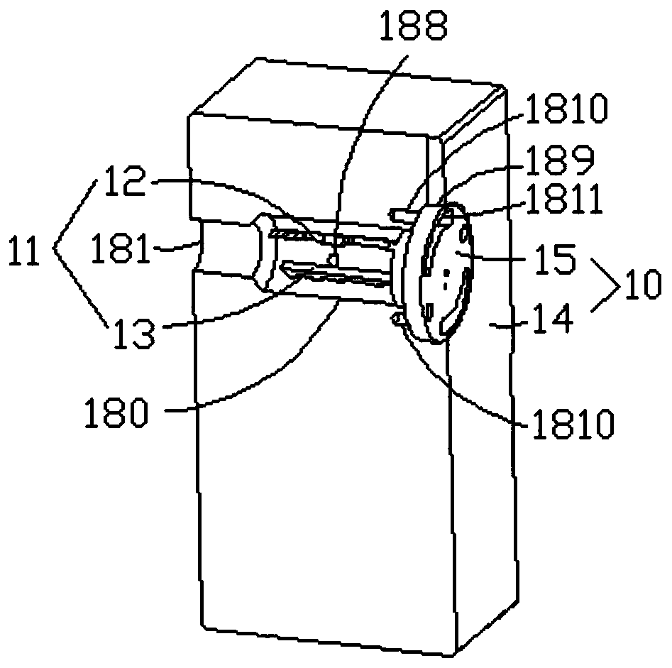
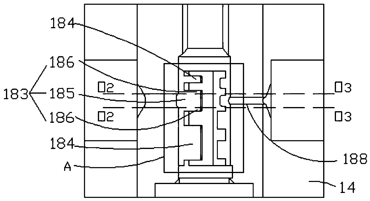
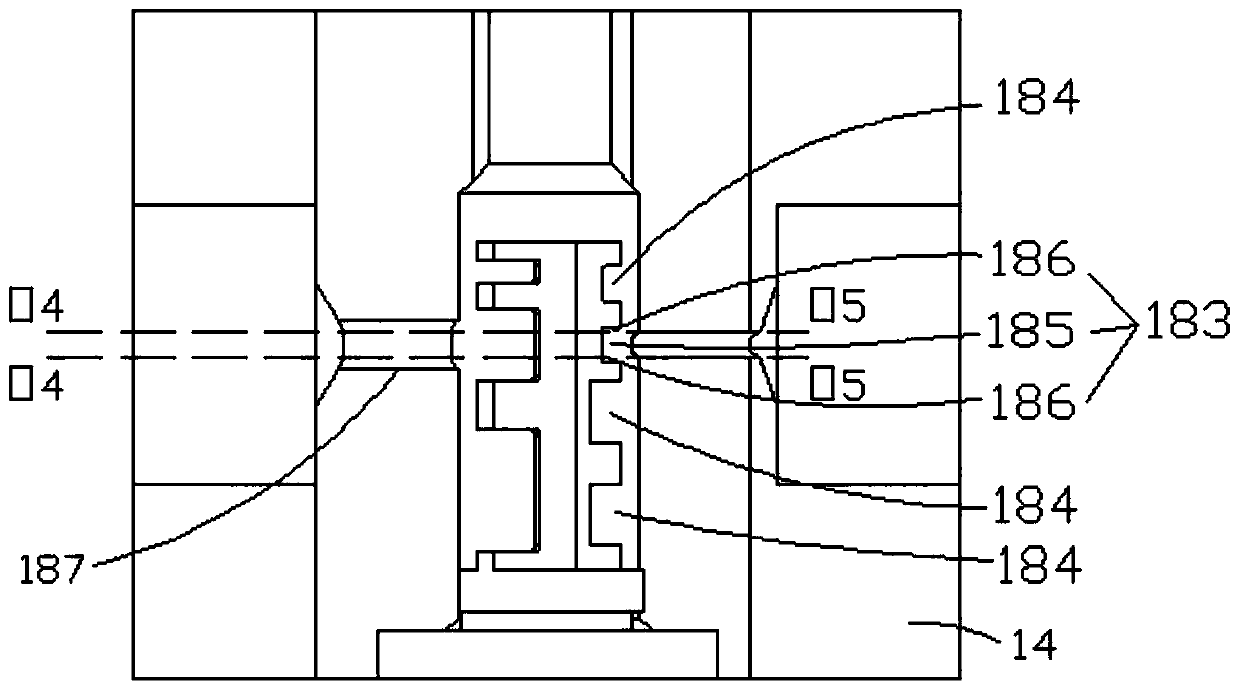
[0037] This embodiment provides a multi-fluid mixer, such as Figure 1 to Figure 3 As shown, it includes a mixing block 10; the mixing block 10 is provided with a cylindrical mixing chamber 180; the top wall and side wall of the mixing chamber 180 are respectively provided with a liquid outlet 181 and a plurality of groups of liquid inlets 182 distributed in a circle; The port 181 and the liquid inlet 182 are both communicated with the outer surface of the mixing block 10; the mixing chamber 180 is provided with a plurality of shunt vane groups corresponding to multiple groups of liquid inlets 182 one-to-one; A number of splitter vanes 11; the splitter vanes 11 are provided with a first flow channel slot 183, and two sets of second flow channel slots 184 distributed on both sides of the first flow channel slot 183; the first flow channel slot 183 and the two sets of second flow channel slots 184 is arranged along the length direction of the mixing chamber 180; the first flow c...
Embodiment 2
[0057] The present embodiment provides a multi-fluid mixer, and the same points with the first embodiment will not be repeated, but the differences are:
[0058] like Figure 4 and Figure 5 As shown, the liquid inlet 182 extends obliquely, and the central axis is perpendicular to the central axis of the mixing chamber 180; the multiple groups of liquid inlets 182 include several groups of main agent ports 187 and several groups of auxiliary agent ports 188;
[0059] The main agent port 187 includes a first front end communicating with the outer surface of the mixing block 10;
[0060] The auxiliary agent port 188 includes a second front end communicating with the outer surface of the mixing block 10;
[0061] The angle formed between the main dose port 187 and the reference line passing through the first front end and the second front end is 0°-35°, that is, the straight line L5 and the straight line OO 1 The formed angle is 0°-35°;
[0062] The angle formed between the a...
Embodiment 3
[0085] The present embodiment provides a hybrid test method, comprising the following steps:
[0086] Step S101:
[0087] Set the first working parameters of the multi-fluid mixer; wherein the first working parameters include: the main agent category, the diameter of the main agent port, the flow rate of the main agent, the flow rate of the main agent entering the mixing chamber, the pushing pressure of the main agent, and the auxiliary agent. The type of the agent, the diameter of the adjuvant port, the flow rate of the adjuvant, the flow rate of the adjuvant entering the mixing chamber, and the pushing pressure of the adjuvant;
[0088] Obtain the Reynolds number of the main agent, the Reynolds number of the auxiliary agent, the second working parameter after the main agent enters the mixing chamber, and the third working parameter after the auxiliary agent enters the mixing chamber; wherein; the second working parameter and the third working parameter are both Including: d...
PUM
 Abstract
Description
Claims
Application Information
 - R&D
- Intellectual Property
- Life Sciences
- Materials
- Tech Scout
- Unparalleled Data Quality
- Higher Quality Content
- 60% Fewer Hallucinations
Browse by: Latest US Patents, China's latest patents, Technical Efficacy Thesaurus, Application Domain, Technology Topic, Popular Technical Reports.
© 2025 PatSnap. All rights reserved.Legal|Privacy policy|Modern Slavery Act Transparency Statement|Sitemap|About US| Contact US: help@patsnap.com


