Jig on lockset production device

A technology for production equipment and fixtures, applied in metal processing equipment, construction locks, manufacturing tools, etc., can solve the problems of single structure, difficult to adjust the position of the lock cylinder, etc., to achieve the effect of easy assembly, easy adjustment, and easy matching

Inactive Publication Date: 2020-04-03
何国标
View PDF9 Cites 2 Cited by
  • Summary
  • Abstract
  • Description
  • Claims
  • Application Information

AI Technical Summary

Problems solved by technology

[0004] The purpose of the present invention is to provide a solution that is accurate in positioning and can be used simultaneously in the treatment of the problem that the lock cylinder assembly equipment fixture structure in the prior art is single, the produced lock cylinder is not paired with a specific key, and the position of the lock cylinder is difficult to adjust. Fixtures on lock production equipment that place lock cylinders and keys and assemble them efficiently

Method used


Image

  • Jig on lockset production device
  • Jig on lockset production device
  • Jig on lockset production device

Examples


Embodiment Construction

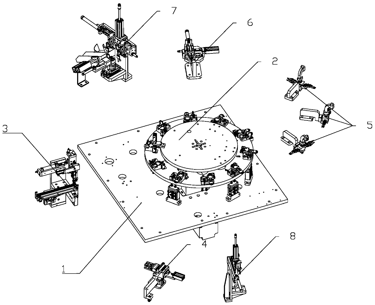
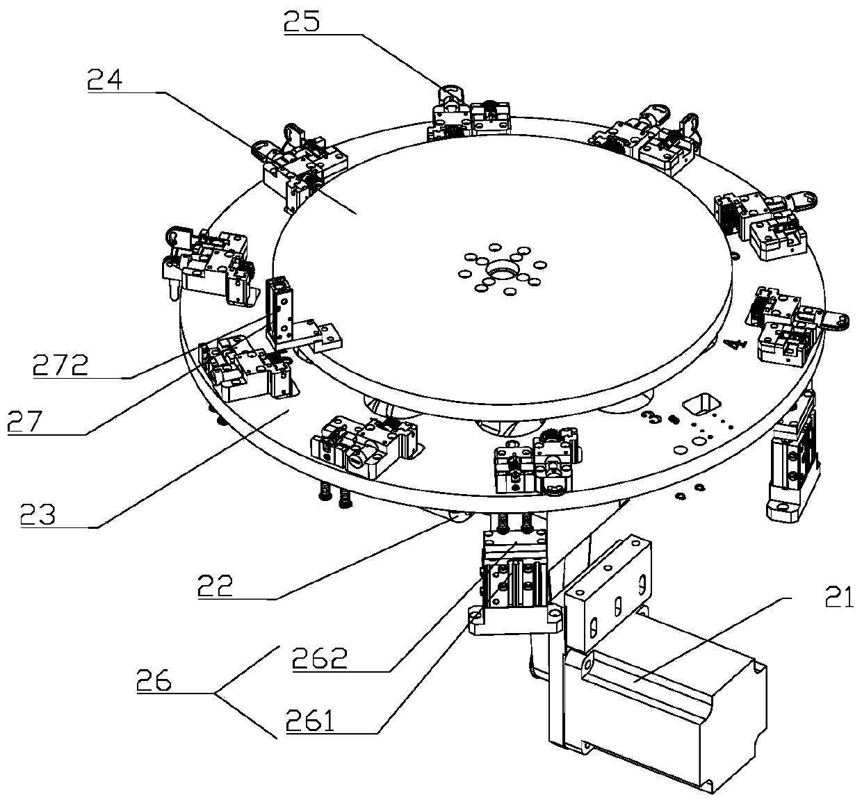
[0022] Such as figure 1 As shown, a lock cylinder spring and lock piece assembly system includes a frame 1, a turntable jig device 2, a lock cylinder feeding device 3, a spring feeding device 4, a lock piece feeding device 5, a key assembly device 6, and a detection device. Material device 7 and key feeding manipulator 8; Turntable fixture device 2 is arranged on the middle part of frame 1, and described lock core feeding device 3, key assembly device 6 and detection blanking device 7 are installed on frame 1, Located on the outside of the turntable jig device 2; the spring feeding device 4 and the lock plate feeding device 5 are installed on the fixed part of the turntable jig device 2; along the direction of processing, the lock core feeding device 3 and the spring feeding device 4. The key feeding manipulator 8, the lock plate feeding device 5, the key assembly device 6 and the detection and unloading device 7 are sequentially connected and arranged; the lock plate feeding ...


PUM


Abstract

The invention relates to the field of lockset production. A jig comprises a lock plug jig body, a cover sheet, an ejecting column, a spring, a rotating seat, a key jig body, a gear and a rack; the upper end of the lock plug jig body is provided with a circular groove, the lock plug jig body is also provided with a transverse sinking groove, the cover sheet is arranged at the side portion of the lock plug jig body, a gap is reserved between the cover sheet and the lock plug jig body, the gap just can allow the flange part of a lock plug to be placed, and the upper end of the cover sheet is provided with a sinking groove; and the upper end of the ejecting column is connected with the lock plug jig body, the outside of the ejecting column is connected with an installation plate through a linear bearing, the rotating seat is fixedly arranged on the installation plate, the key jig body is rotationally connected in the rotating seat, a rectangular hole allowing a key to be placed is formed in the key jig body, the gear is arranged at the other end of the key jig body, the rack meshes with the gear and is movably connected with the rotating seat, and a circular hole is formed in the rightside of the rack. The jig has the advantages of accurate positioning effect, adoption of the two jig bodies and high assembly efficiency.

Description

technical field [0001] The invention relates to the field of lock production, in particular to a fixture on lock production equipment. Background technique [0002] The lock cylinder is an important part of the lock. The lock cylinder adopts multiple anti-theft technologies, a variety of special-shaped anti-pulling pins, and prevents technical opening. With the unique pin and blade structure design, it has a high security performance against technical opening. Due to the small and precise structure of the lock cylinder, the efficiency of the traditional manual assembly process is low. In automated production, specific jigs are generally set to position the assembled parts. [0003] The China State Intellectual Property Office has published a publication number of CN109676373A, and the patent name is a patent for a lock cylinder assembly mechanism and the lock cylinder assembly mechanism thereof. The patent includes a lock cylinder feeding device, a lock cylinder assembly ass...

Claims


Application Information

Patent Timeline
IPC IPC(8): B23P19/00E05B17/00
CPCB23P19/00B23P19/001B23P19/007E05B17/0004
Inventor 何国标王德胜杨道济
Owner 何国标
Why Eureka
Try Eureka