Assembling equipment for rotatable inductive probe

A technology of induction probe and assembly equipment, which is applied in assembly machines, metal processing equipment, positioning devices, etc., can solve the problems of large loss rate, poor induction detection effect, and limited fixed detection range. The effect of good detection effect and long service life

Active Publication Date: 2020-04-03
深圳市鑫康医疗器械有限公司
View PDF9 Cites 0 Cited by
  • Summary
  • Abstract
  • Description
  • Claims
  • Application Information

AI Technical Summary

Problems solved by technology

[0002] Inductive probe is a device that receives signals or stimuli and reacts. It can convert the physical or chemical quantity to be measured into another corresponding output device, and most of them are stimulated by electrical signals, and inductive probes are mostly used in machinery manufacturing and industrial process control. , automotive electronic products, communication electronic products, consumer electronic products and special equipment, etc., but the probe part of the existing induction probe is mostly fixed, and the induction probe is fixed at the designated position, the detection range is fixed and limited, and the external environment changes The strain capacity of the sensor is poor, and the induction detection effect is poor. At the same time, the existing induction probe is easily disturbed by the external environment, and the breakage rate is large, which affects the detection accuracy. Therefore, it is necessary to improve the structure of the existing induction probe to adapt to different detection. environmental needs

Method used


Image

  • Assembling equipment for rotatable inductive probe
  • Assembling equipment for rotatable inductive probe
  • Assembling equipment for rotatable inductive probe

Examples


Embodiment 1

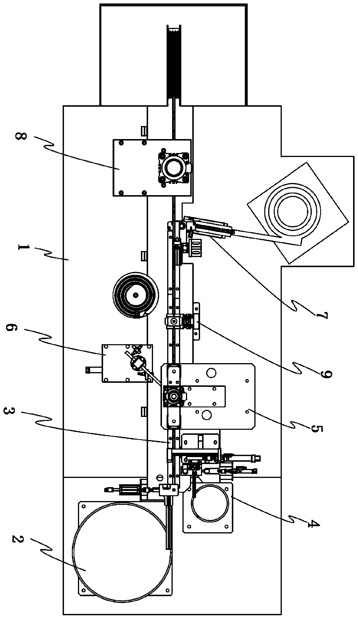
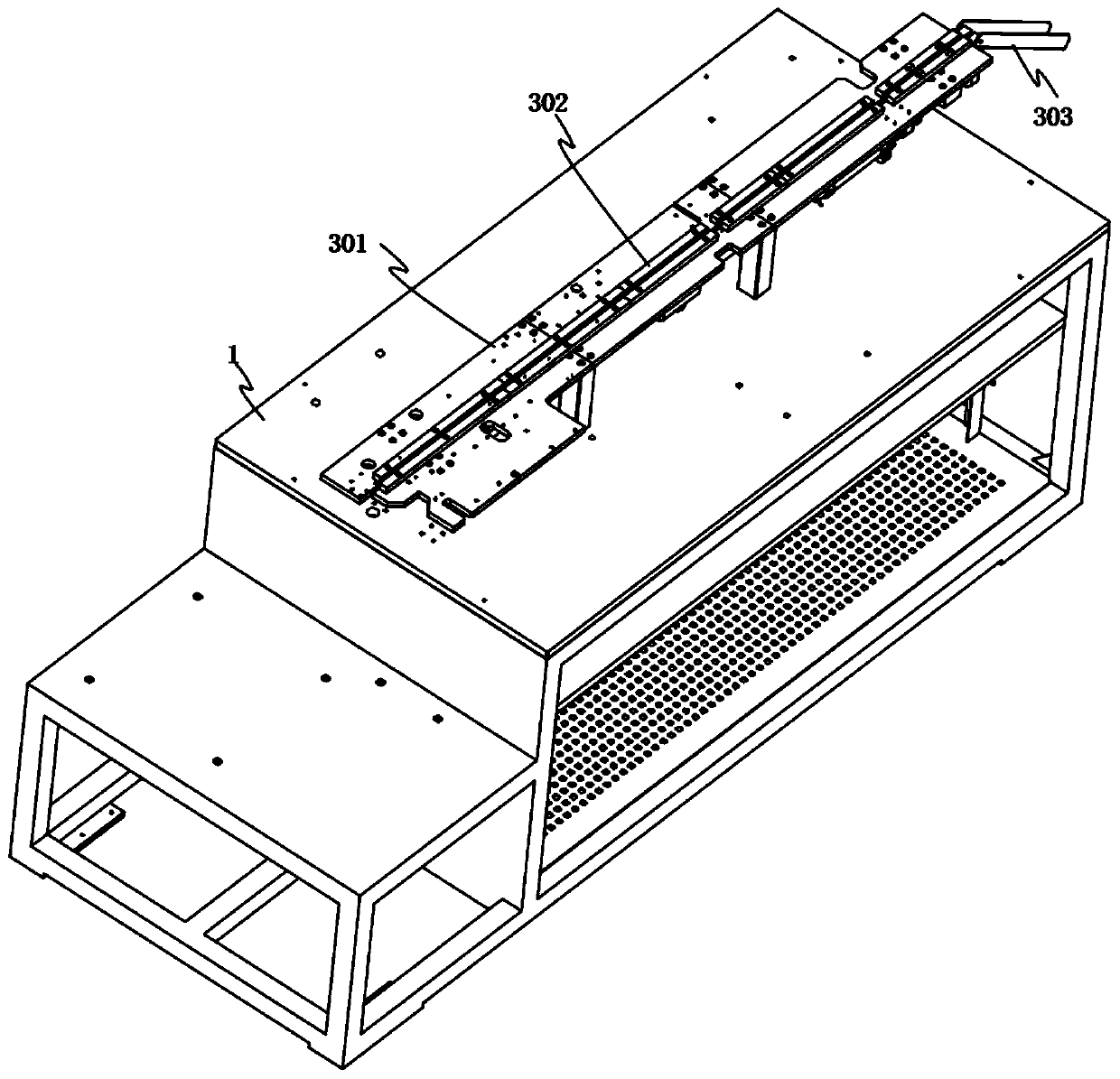
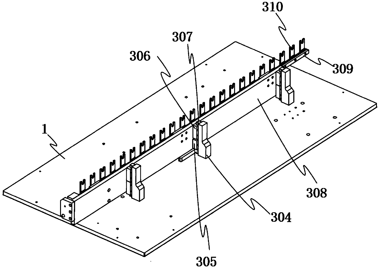
[0037] When the assembly equipment is working, the bottom cover is first output by the conveying vibrating plate I201 of the bottom cover input mechanism 2 along the conveying groove strip I202 on the output port one by one, and the bottom cover pushing block 204 is driven by the ejection cylinder I203 to put the conveying groove strip I202 on the mouth The bottom cover is pushed onto the conveying slat mechanism 3, and then the lifting cylinder I305 of the conveying slat mechanism 3 moves upward along the vertical slide rail 307 by driving the displacement block 306, thereby driving the shift push block 310 upward along the vertical slide rail 307 Move into the horizontal groove bar 302 and jack up the bottom cover, and then drive the horizontal displacement slat 309 to move forward by the displacement cylinder 311, thereby driving the shift push block 310 to move in the horizontal groove bar 302, so as to drive the bottom cover along the The horizontal groove bar 302 moves to...

Embodiment 2

[0039] After the threaded bearing is placed on the bottom cover, the bottom cover is transferred to the bottom of the induction probe pressing mechanism 5 by the conveying slat mechanism 3, and then the conveying vibrating plate III 611 of the induction probe delivery mechanism 6 conveys the induction probes to the conveying mouth one by one, Then, the rotary drive cylinder 612 is driven by the drive gear 609 and the drive rack 610 to drive the rotary block 602 to rotate, and the suction nozzle 608 at the free end of the top ventilation rod 607 is moved to the upper part of the induction probe on the delivery port of the delivery vibrating plate III 611, and then The ventilation rod 607 on the lifting block 606 is driven by the lifting cylinder 604 to move down, so that the suction nozzle 608 at the free end of the ventilation rod 607 moves down to absorb the induction probe on the delivery port of the conveying vibration plate III 611, and then the cylinder is driven by rotatio...

Embodiment 3

[0041] The conveying vibrating plate IV 701 of the cap input mechanism 7 outputs the caps one by one along the conveying groove III 702, and then the horizontal drive cylinder II 705 is driven by meshing with the driving gear 708 through the horizontal rack 707 to rotate the clamping cylinder 710 on one side of the rotating plate 709 To the upper part of the notch of the conveying trough III 702, then clamp the cylinder 710 to drive the jaw 711 to pick up the cap on the notch of the conveying trough III 702, and then drive the cylinder II 705 horizontally through the horizontal rack 707 and the drive gear 708 to drive the rotation The clamping cylinder 710 that grabs the cap on the plate 709 rotates to the upper part of the chassis, and then the vertical displacement plate body 706 is driven vertically down by the vertical drive cylinder III 704, and then the cap is placed on the chassis by the clamping cylinder 710, and then The chassis covered with caps is conveyed to the low...


PUM


Abstract

The invention relates to assembling equipment for a rotatable inductive probe. The assembling equipment comprises an assembling table body and a conveying slat mechanism arranged on the assembling table body, wherein a bottom cover input mechanism is arranged at the input port end of the conveying slat mechanism, a cross-under bearing input mechanism is arranged on one side of an input port of theconveying slat mechanism, an inductive probe delivery mechanism is arranged on one side of the rear portion of the cross-under bearing input mechanism, an inductive probe press fitting mechanism is arranged on the other side of the rear portion of the cross-under bearing input mechanism, the conveying slat mechanism is provided with an oil injection mechanism at one edge of the rear portion of the inductive probe press fitting mechanism, a cover cap input mechanism is arranged at one edge of the rear portion of the oil injection mechanism, and a cover cap press fitting mechanism is arranged at one edge of the rear portion of the cover cap input mechanism. The inductive probe assembled by the assembling equipment is not only added with a protective outer shell but also can be rotated and positioned, the assembled inductive probe is not only not easily affected by the external environment but also can make a positive respond to the external environment, the damage rate of the inductiveprobe is low, the service life is long, and the probe effect is good.

Description

technical field [0001] The invention relates to the technical field of sensor assembly equipment, in particular to an assembly equipment for a rotatable induction probe. Background technique [0002] Inductive probe is a device that receives signals or stimuli and reacts. It can convert the physical or chemical quantity to be measured into another corresponding output device, and most of them are stimulated by electrical signals, and inductive probes are mostly used in machinery manufacturing and industrial process control. , automotive electronic products, communication electronic products, consumer electronic products and special equipment, etc., but the probe part of the existing induction probe is mostly fixed, and the induction probe is fixed at the designated position, the detection range is fixed and limited, and the external environment changes The strain capacity of the sensor is poor, and the induction detection effect is poor. At the same time, the existing induct...

Claims


Application Information

Patent Timeline
IPC IPC(8): B23P21/00B23P19/027B23Q3/08
CPCB23P19/001B23P19/002B23P19/007B23P19/027B23P21/004B23Q3/08
Inventor 王毅军
Owner 深圳市鑫康医疗器械有限公司
Why Eureka
Try Eureka