Grinding device and grinding method

A grinding device and grinding head technology, applied in grinding devices, grinding machine tools, manufacturing tools, etc., can solve the problems of uneven hydraulic pressure of the retainer, uneven grinding pressure, and complex structure.

Active Publication Date: 2022-03-29
SUMCO CORP
View PDF5 Cites 0 Cited by
  • Summary
  • Abstract
  • Description
  • Claims
  • Application Information

AI Technical Summary

Problems solved by technology

[0010] However, as mentioned above, in reality, the amount of protrusion of the wafer is not uniform due to the wear of the retaining ring or the non-uniformity of the thickness dimension of the wafer, and the hydraulic pressure of the holder is also not uniform.
With the uneven hydraulic pressure of the retainer, the grinding pressure will also become uneven, and as a result, the grinding allowance will be uneven.
[0011] In the case of using a polishing head in which the wafer chuck and the retaining ring are integrated as described above, since the relative position of the wafer chuck and the retaining ring cannot be changed, the protruding amount of the wafer cannot be controlled per batch, and the above problems cannot be solved. problem
[0012] On the other hand, in the polishing apparatus described in Document 1, by independently driving the wafer chuck and the holding ring, the amount of protruding wafers can be controlled per batch, but for independently driving the wafer chuck and the holding ring The structure is complex, and there are problems that require more sensors or control components

Method used


Image

  • Grinding device and grinding method
  • Grinding device and grinding method
  • Grinding device and grinding method

Examples


no. 1 Embodiment approach

[0050] Hereinafter, a first embodiment of the present invention will be described with reference to the drawings.

[0051] In addition, in this embodiment, the setting process of the grinding conditions (head pressing force, table rotation speed, grinding time) based on the retainer hydraulic pressure is performed for each batch (once in a batch) is exemplified. structure, but it can also be done multiple times in 1 batch.

[0052] [Structure of grinding device]

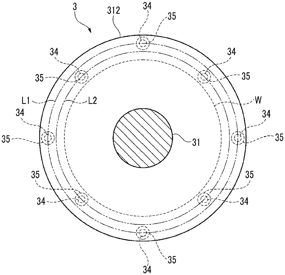
[0053] Such as figure 1 and figure 2 As shown, the polishing device 1 is a single-chip device for finely grinding the surface of a wafer W having a diameter of 300 mm. In addition, the polishing apparatus 1 may be used as a target wafer W whose diameter size is other than 300 mm.

[0054] This grinding device 1 is provided with grinding part 2, four grinding heads 3, grinding head driving mechanism 4 (referring to Figure 5 ), storage mechanism 5 (reference Figure 5 ) and control mechanism 6 (refer to Figur...

no. 2 Embodiment approach

[0106] Next, a second embodiment of the present invention will be described.

[0107] In addition, the major difference between the second embodiment and the first embodiment is the polishing process of the wafer W, and the structure of the polishing apparatus 1 is the same as that of the first embodiment.

[0108] First, if Figure 7 As shown, the polishing control mechanism 61 and the four cage hydraulic pressure measurement mechanisms 35 of the polishing apparatus 1 perform the same processes of steps S1 to S3 as those in the first embodiment.

[0109] When the retainer hydraulic pressure measurement results from the four retainer hydraulic pressure measurement means 35 are obtained, the parameter setting means 62 calculates a value related to the inclination of the retainer ring 33 from the four retainer hydraulic pressure Fr (step S14 ).

[0110] The inclination related value is a value indicating the inclination of the lower surface of the holding ring 33 with respect t...

Embodiment approach

[0122] In addition, this invention is not limited to the said embodiment, Various improvement, a design change, etc. are possible in the range which does not deviate from the summary of this invention.

[0123] That is, in the first embodiment, the following configuration can be adopted.

[0124] As the relational expression for calculating the predicted value of the grinding allowance, the above-mentioned mathematical expression (1) is used, but for example, it is also possible to newly introduce a parameter related to the retainer hydraulic pressure Fr, and use the above-mentioned mathematical expression ( 1) Different relational formulas are used to calculate the predicted value of the grinding allowance.

[0125] When the newly measured retainer hydraulic pressure Fr is greater than the retainer hydraulic pressure Fr measured in the immediately preceding batch, at least one parameter among the grinding head pressure Fh, platform speed R, and batch grinding time Tb can only...


PUM

PropertyMeasurementUnit
diameteraaaaaaaaaa

Abstract

A grinding device (1) provided with a grinding head (3) in which a liner (32) and a retaining ring (33) are integrated, which comprises: a retainer hydraulic pressure measurement mechanism (35), during grinding of a wafer (W) Measure the retainer hydraulic pressure (Fr) that the retainer ring (33) receives from the slurry (P) on the grinding pad (23); and the parameter setting mechanism, based on the retainer hydraulic pressure measured by the retainer hydraulic pressure measuring mechanism (35) (Fr) to set at least one parameter in the grinding head pressure (Fh) given to the grinding head (3), the rotating speed of the platform (22) and the grinding time of each batch, the grinding control mechanism is set according to the parameters. At least one of the rotary driving mechanism and the grinding head pressurizing mechanism is controlled by parameters set by the setting mechanism.

Description

technical field [0001] The invention relates to a grinding device and a grinding method. Background technique [0002] A polishing method using a polishing head in which a wafer chuck and a holding ring are integrated is known as a polishing method used in a finish grinding step of a semiconductor wafer (hereinafter referred to as wafer). In this polishing method, a wafer is held on a polishing head, a slurry is supplied onto a polishing pad, and the wafer is polished in a state where a holding ring is not in contact with the polishing pad. [0003] On the other hand, there is known a polishing device in which a wafer chuck and a holding ring are independently driven (for example, Document 1: Japanese Patent Application Laid-Open No. 2009-107094). The polishing apparatus of this document 1 includes a rubber membrane provided on the surface (back surface) of the wafer chuck, and the pressure for pressing the wafer against the polishing pad is controlled by controlling the pr...

Claims


Application Information

Patent Timeline
Patent Type & Authority Patents(China)
IPC IPC(8): B24B37/04B24B37/10B24B37/32B24B37/34
CPCB24B37/00B24B37/34B24B1/00
Inventor 小佐佐和明杉森胜久
Owner SUMCO CORP
Why Eureka
Try Eureka