
Intelligent setting-out device for rail traffic cable

A kind of rail transit cable, intelligent technology, applied in the direction of conveyor objects, conveying filamentous materials, thin material processing, etc., can solve the problem of slow pay-off work efficiency, unsteady and smooth outlet, and scratches and damages at the end of the cable. and other problems, to achieve the effect of flexible adjustment of the position of the pay-off, efficient work of the pay-off, and guarantee of extensiveness.

Active Publication Date: 2020-04-03
苏州科亿嘉科技发展有限公司
View PDF19 Cites 3 Cited by
  • Summary
  • Abstract
  • Description
  • Claims
  • Application Information

AI Technical Summary

Problems solved by technology

[0004] The purpose of the present invention is to solve the problem that the existing pay-off equipment can only adapt to the track of the same width for mobile pay-off work, and cannot flexibly adjust the matching distance between the electric wheel on the pay-off equipment and the rail plate on the track , the working mode of the pay-off equipment is single; and the efficiency of the pay-off work is slow; the stability and firmness of the pay-off equipment are poor when working; Inaccurate and suitable; during the pay-off process of the pay-off device, the cable is prone to entanglement or scratching; when the length of the cable wound on the pay-off device is too short, the cable is wound and fixed on the pay-off device Insufficient fastening, causing the end of the cable to fall to the ground when the pay-off equipment is not unwound, causing scratches and damage; Intelligent pay-off equipment for rail transit cables

Method used


Image

  • Intelligent setting-out device for rail traffic cable
  • Intelligent setting-out device for rail traffic cable
  • Intelligent setting-out device for rail traffic cable

Examples


Embodiment Construction

[0046] The technical solutions of the present invention will be clearly and completely described below in conjunction with the embodiments. Apparently, the described embodiments are only some of the embodiments of the present invention, not all of them. Based on the embodiments of the present invention, all other embodiments obtained by persons of ordinary skill in the art without creative efforts fall within the protection scope of the present invention.

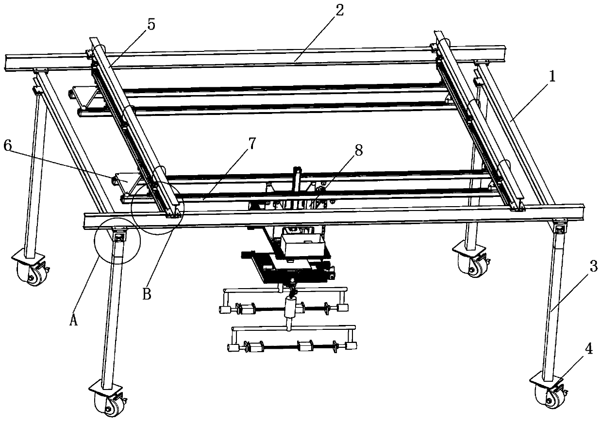
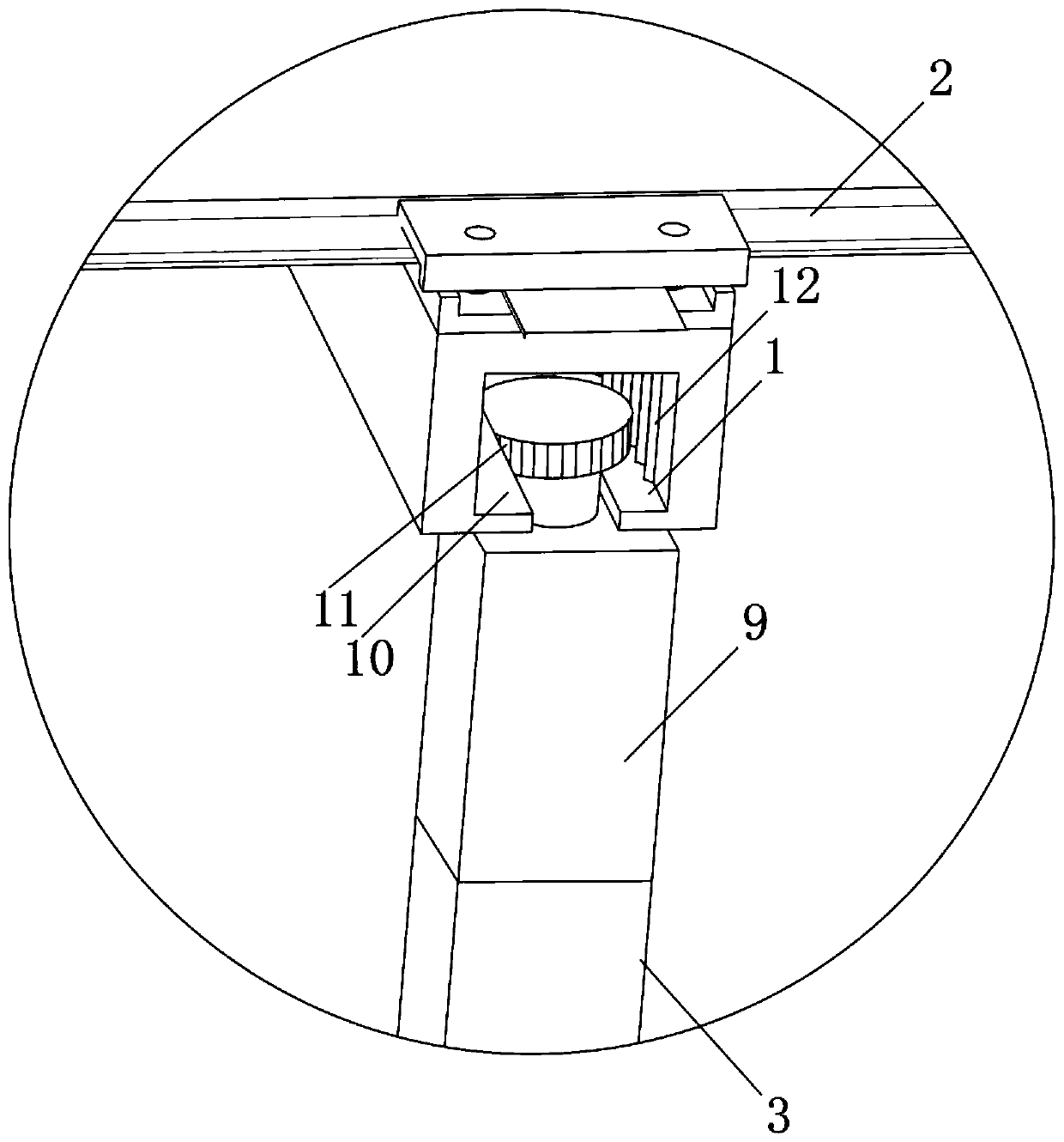
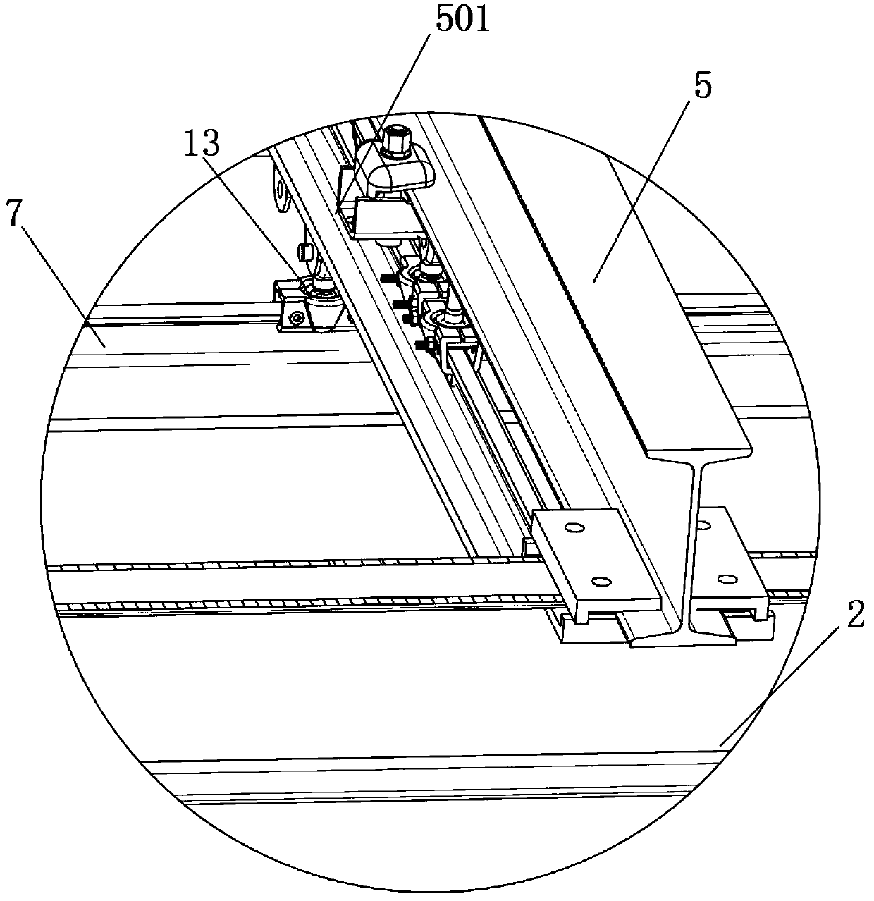
[0047] see Figure 1-12 As shown, an intelligent pay-off device for rail transit cables includes two side casing frames 1, two upper end plates 2, two top loading frames 5 and a transfer plate 8, and the two side casing frames 1 are arranged in parallel , and the two upper end plates 2 are respectively arranged at the two ends between the two side cover frames 1, vertical support rods 3 are arranged vertically below the two ends of the two side cover frames 1, and both sides above the two upper end plates 2 are Top loading...


PUM


Abstract

The invention discloses an intelligent setting-out device for a rail traffic cable. The device comprises two side sleeving frames I, two upper end plates, two top carrying frames and a transfer disk,wherein the two side sleeving frames are disposed in parallel; the two upper end plates are disposed on two ends between the two side sleeving frames I; vertical struts are vertically disposed under two ends of the two side sleeving frames; and the top carrying frames are disposed on two sides above the upper end plates. The device disclosed by the invention has the beneficial effects that a motorI on the top of the vertical struts is fitted with rolling of rolling teech I in a rolling slot I by a gear I so as to adjust an interval between the vertical struts on two sides of the device, and thus electric wheels can be arranged on rail plates which are located on two sides of rails with different widths. On one side, the device is connected to the two sides of the rail by the electric wheels and the device can be driven to realize movable work, so the device can carry out setting-out work more efficiently; and on the other side, the device can be fitted with the rails which have different widths, so extensive fitting is ensured, and the device can move on the rails more stably and smoothly.

Description

technical field [0001] The invention relates to a pay-off device, in particular to an intelligent pay-off device for rail transit cables, and belongs to the technical field of pay-off device applications. Background technique [0002] In the process of rail transit cable laying, pay-off equipment is indispensable. The cable is wound on the pay-off equipment, and the cable is walked on the track through the pay-off equipment, and the cable is paid out to facilitate the laying of cables in the track. . [0003] There are still many deficiencies in the existing pay-off equipment when in use. The existing pay-off equipment can only be adapted to the track of the same width for mobile pay-off work, and cannot flexibly adjust the electric wheels on the pay-off equipment. The matching distance of the rail plate on the track, the working mode of the pay-off equipment is single, and the efficiency of the pay-off work is slow, the stability and firmness of the pay-off equipment are p...

Claims


Application Information

Patent Timeline
Patent Type & Authority Applications(China)
IPC IPC(8): B65H49/20B65G47/90
CPCB65G47/90B65H49/20
Inventor 沈美莲
Owner 苏州科亿嘉科技发展有限公司
Learn More