
Flash evaporator and refrigerating system

A technology of refrigeration system and flash evaporator, which is applied in the field of flash evaporator and refrigeration system, and can solve problems such as incomplete gas-liquid separation, suction with liquid, damage to the compressor, etc.

Pending Publication Date: 2020-04-03
GREE ELECTRIC APPLIANCES INC
View PDF0 Cites 0 Cited by
  • Summary
  • Abstract
  • Description
  • Claims
  • Application Information

AI Technical Summary

Problems solved by technology

[0004] In the embodiment of the present invention, a flash evaporator and a refrigeration system are provided to solve the problem of incomplete gas-liquid separation in the flash evaporator in the prior art, which may easily cause liquid in the high-pressure stage suction and damage the compressor.

Method used


Image

  • Flash evaporator and refrigerating system
  • Flash evaporator and refrigerating system

Examples


Embodiment Construction

[0020] The present invention will be described in further detail below in conjunction with the accompanying drawings and specific embodiments, but not as a limitation of the present invention.

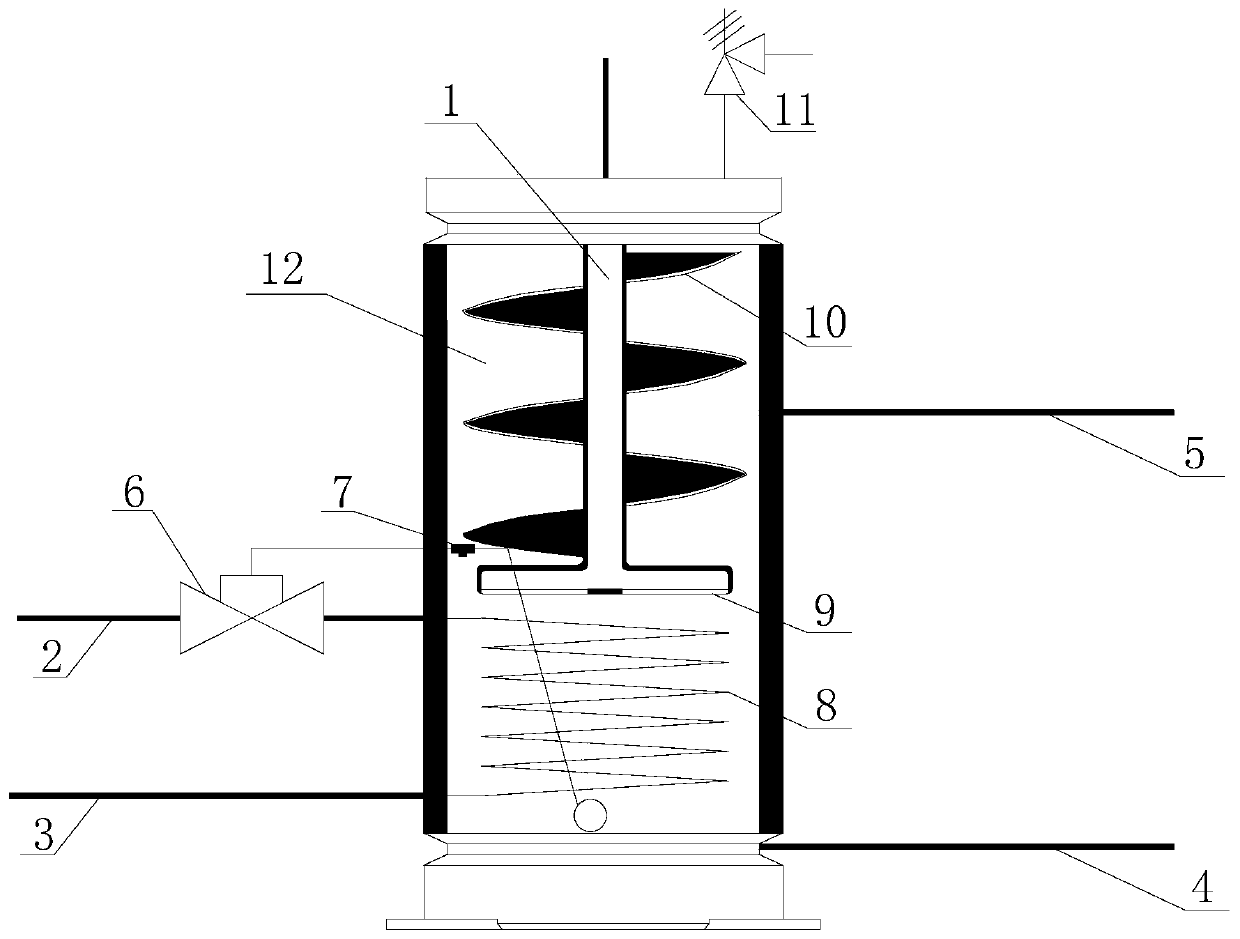
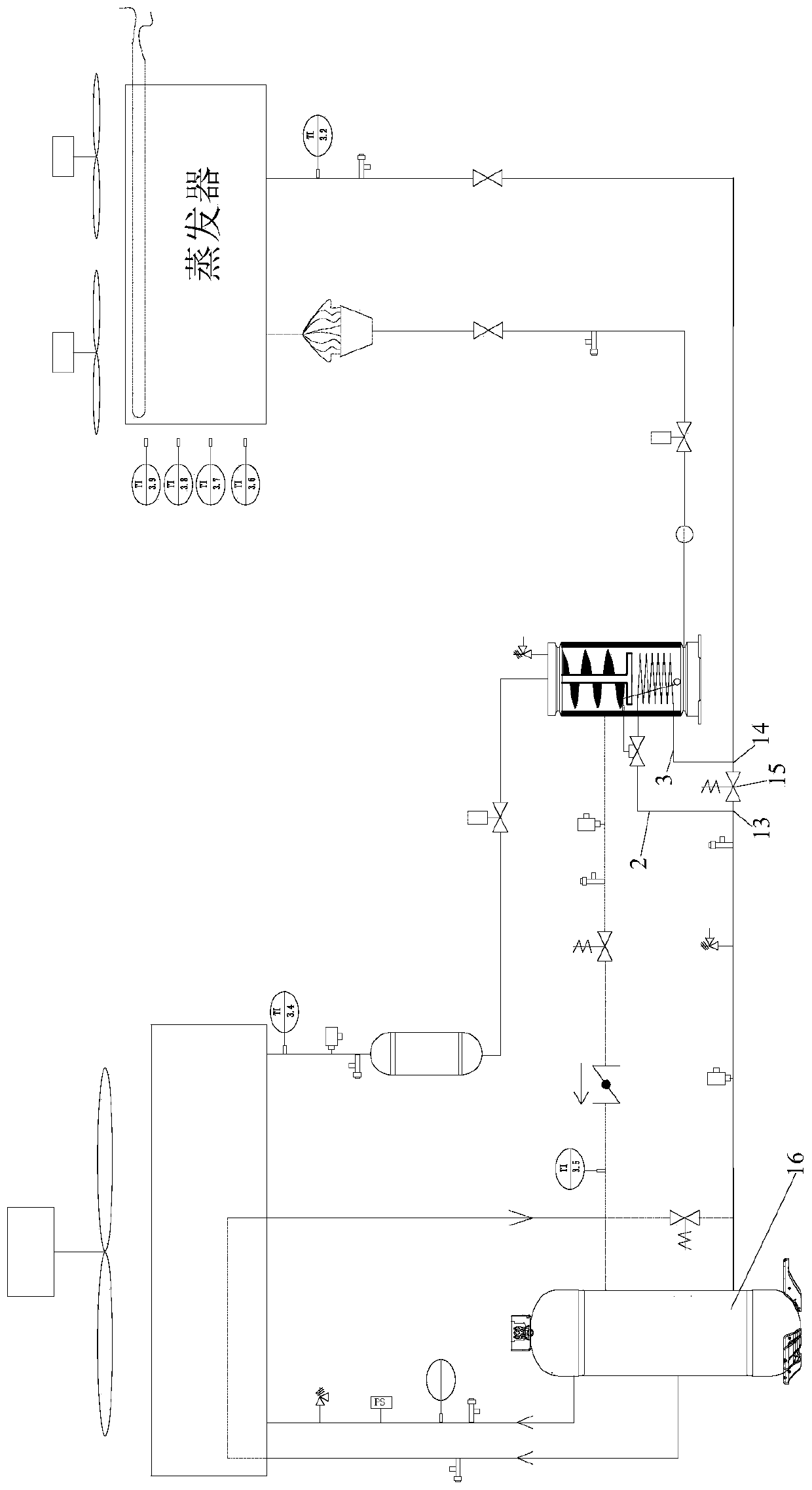
[0021] see figure 1 As shown, according to an embodiment of the present invention, an embodiment of a flash evaporator is provided. The flash evaporator includes an inner cavity 12 for two-phase separation, and the flash evaporator also includes an inlet pipe 1, a heat exchange tube 8, and a microchannel structure 9 and the centrifugal disc 10, the inlet pipe 1 is located in the inner cavity 12; the heat exchange tube 8 is arranged at the bottom of the inner cavity 12, the heat exchange tube 8 is connected with the suction pipeline of the compressor, and the heat exchange tube 8 flows into the compressor Refrigerant before the suction port; the microchannel structure 9 is connected to the end of the inlet pipe 1, the microchannel structure 9 is located above the heat exchange tube 8, a...


PUM


Abstract

The invention discloses a flash evaporator and a refrigerating system. The flash evaporator comprises an inner cavity, and further comprises an inlet tube, a heat exchange tube, a micro-channel structure and a centrifugal pan, wherein the inlet tube is located in the inner cavity; the heat exchange tube is arranged at the bottom part of the inner cavity; the heat exchange tube communicates with anair suction pipeline of a compressor; a refrigerant before entering an air suction port of the compressor flows in the heat exchange tube; the micro-channel structure is connected with the tail end of the inlet tube; the micro-channel structure is located above the heat exchange tube; the liquid refrigerant in the inlet tube is adhered to the heat exchange tube after passing through the micro-channel structure; the centrifugal pan is located in the inner cavity; the centrifugal pan spirally sheathes the inlet tube; the flash evaporator is provided with an air supplement port; and the air supplement port and the centrifugal pan are correspondingly arranged in position. The flash evaporator and the refrigerating system effectively solve the problem that a compressor is damaged due to the fact that high-pressure stage liquid entrainment during air suction is easily caused by the fact that gas-liquid separation of a flash evaporator is not thorough in the prior art.

Description

technical field [0001] The invention relates to the technical field of refrigeration systems, in particular to a flash evaporator and a refrigeration system. Background technique [0002] CO 2 As the latest generation of refrigerant, its transcritical cycle is currently being used more and more widely in the refrigeration industry, such as container refrigeration units, automotive air conditioners, heat pump water vapor, commercial refrigerators and other systems. Due to CO 2 Under normal conditions, the pressure is high and the boiling point is low. In a supercritical cycle, two-stage compression is usually required. A flash evaporator is required between the low-pressure stage and the high-pressure stage to achieve rapid vaporization of the fluid and separation of the two phases. There are following deficiencies in the flash evaporator in the prior art: [0003] Most of the flash evaporators adopt large-space sedimentation and separation, and the gas-liquid separation i...

Claims


Application Information

Patent Timeline
IPC IPC(8): F25B43/00F25B41/00F25B9/00
CPCF25B43/00F25B9/008F25B41/40
Inventor 何汝龙齐方成韩鹏
Owner GREE ELECTRIC APPLIANCES INC
Learn More