Electric instrument damping base

A technology of power meter and shock-absorbing base, which is applied to springs/shock absorbers, parts and instruments of electrical measuring instruments, etc., can solve the problem of inaccurate accuracy and sensitivity, inability to play a role in shock-absorbing protection, and damage to power meters. and other problems to achieve the effect of increasing convenience, reducing vibration, and prolonging service life

Inactive Publication Date: 2020-04-03
李裕谋
View PDF0 Cites 5 Cited by
  • Summary
  • Abstract
  • Description
  • Claims
  • Application Information

AI Technical Summary

Problems solved by technology

[0003] As an advanced intelligent and digital front-end acquisition component of the power grid, power meters have relatively high requirements for accuracy and sensitivity. At present, some power meters cannot play a good role in shock absorption and protection during use. It may make its accuracy and sensitivity inaccurate, and may damage the power meter

Method used


Image

  • Electric instrument damping base
  • Electric instrument damping base
  • Electric instrument damping base

Examples


Embodiment 1

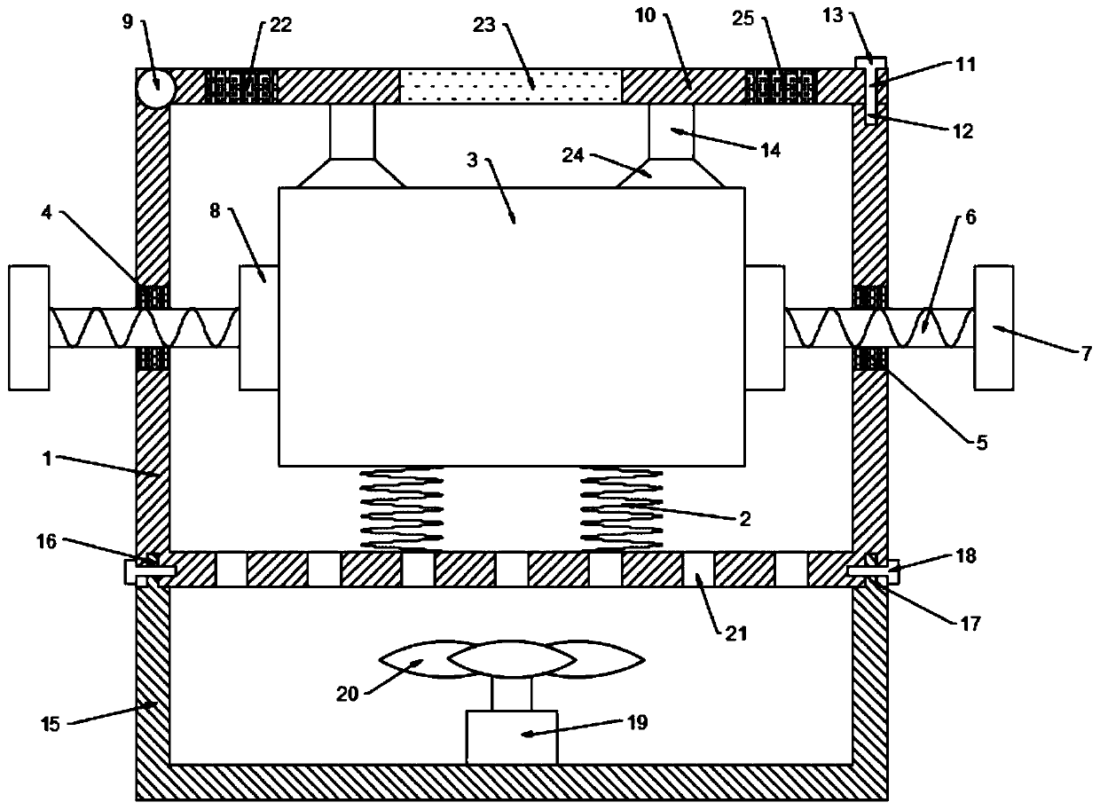
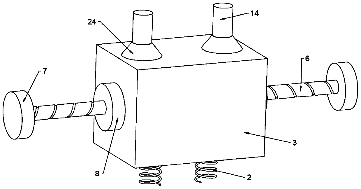
[0020] see Figures 1 to 3 In the embodiment of the present invention, a shock-absorbing base for a power meter includes a housing 1, a spring 2 is arranged on the inner bottom surface of the housing 1, a power meter 3 is connected to the end of the spring 2, and the left and right side walls of the housing 1 are provided There is a through hole 1 4, a nut 5 is installed in the through hole 1 4, and the nut 5 is threadedly connected with a screw rod 6, and one end of the screw rod 6 is located on the outer side of the casing 1. The screw 6 is located inside the casing 1 and one end is fixedly connected with a clamping block 8. The clamping block 8 is located on both sides of the power meter 3. By placing the power meter 3 on the spring 2 in the casing 1, the handle 7 is rotated. , rotate the screw 6 on the nut 5, move the clamping block 8 to the middle, and clamp and fix the power meter 3 so that it cannot shake left and right. Vibration affects its sensitivity.

[0021] The...

Embodiment 2

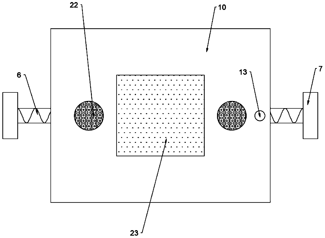
[0027] In order to facilitate the observation of the situation of the power meter 3 in the casing 1, this embodiment is further improved on the basis of the embodiment 1. The improvement is: the cover plate 10 is provided with an observation board 23, through which the observation board 23 can be observed. In the case of the power meter 3 in the casing 1, the cover 10 cannot be opened, which increases the convenience of the device.

[0028] The working principle of this embodiment is: in order to facilitate the observation of the situation of the power meter 3 in the casing 1, an observation board 23 is provided on the cover plate 10, and the situation of the electric power meter 3 in the casing 1 can be observed through the observation board 23. , the cover 10 cannot be opened, which increases the convenience of the device.

[0029] To sum up, by setting the spring 2, the shaking of the power meter 3 can be reduced and the sensitivity of the power meter 3 can be prevented fro...


PUM


Abstract

The invention discloses a damping base of an electric power instrument, which comprises a shell, a spring is arranged on the bottom surface in the shell; the tail end of the spring is connected with apower meter; first through holes are formed in the left side wall and the right side wall of the shell. A nut is mounted in the through hole I; screw rod in threaded connection with nut, a handle isfixedly connected to the end, located on the outer side of the shell, of the screw. The screw rod can rotate on the nut through the handle; a clamping block is fixedly connected to the end, located inthe shell, of the screw rod, the clamping blocks are located on the two sides of the electric power instrument, the electric power instrument is placed on a spring in the shell, a handle is rotated to enable the screw rod to rotate on a nut, the clamping blocks are moved towards the middle, the electric power instrument is clamped and fixed, and the electric power instrument cannot swing left andright; by arranging the spring, shaking of the electric instrument can be reduced, and the sensitivity of the electric instrument is prevented from being affected by vibration; by arranging the screwrod and the rotatable handle, the screw rod rotates on the nut, the clamping block moves towards the middle, and the electric power instrument is clamped and fixed.

Description

technical field [0001] The invention relates to the field of electric devices, in particular to a shock-absorbing base of an electric power meter. Background technique [0002] Power meter is a power measurement and control equipment that provides solutions for power parameter measurement, power quality monitoring and analysis, and electrical equipment control. Multi-function smart meters such as transmission output can complete electricity measurement, energy measurement, data display, acquisition and transmission. The measurement accuracy is 0.5 grade, realizes LED on-site display and remote RS-485 digital interface communication, adopts the communication protocol, the intelligent power meter can be used as a single meter, replacing a large number of traditional analog meters, and can also be used as the front-end equipment of the power monitoring system. Remote data acquisition and control, RS485 communication interface in line with industrial standards, making networkin...

Claims


Application Information

Patent Timeline
Patent Type & Authority Applications(China)
IPC IPC(8): G01R1/04G01R1/02F16F15/067
CPCF16F15/067G01R1/02G01R1/0408
Inventor 李裕谋
Owner 李裕谋
Why Eureka
Try Eureka