Method and system for testing time measurement precision of digital relay protection tester

A time measurement and relay protection technology, which is applied in measurement devices, measurement of electrical variables, instruments, etc., can solve the problems of low action time accuracy, inability to obtain action time measurement results, and low accuracy.

Active Publication Date: 2020-04-03
XUCHANG KETOP DETECTION TECH CO LTD +1
View PDF7 Cites 3 Cited by
  • Summary
  • Abstract
  • Description
  • Claims
  • Application Information

AI Technical Summary

Problems solved by technology

[0004] However, there are many disadvantages in the existing test methods: first, the digital relay protection device and intelligent terminal device used in the test have a relatively fixed operating time, and it is impossible to obtain the measurement results of the operating time in the full range; second, the accuracy of the operating time Relatively low, with large fluctuations; Third, the accuracy of the network message recording and analysis device for marking hard-in and hard-out signals is relatively low

Method used


Image

  • Method and system for testing time measurement precision of digital relay protection tester
  • Method and system for testing time measurement precision of digital relay protection tester
  • Method and system for testing time measurement precision of digital relay protection tester

Examples


Embodiment 1

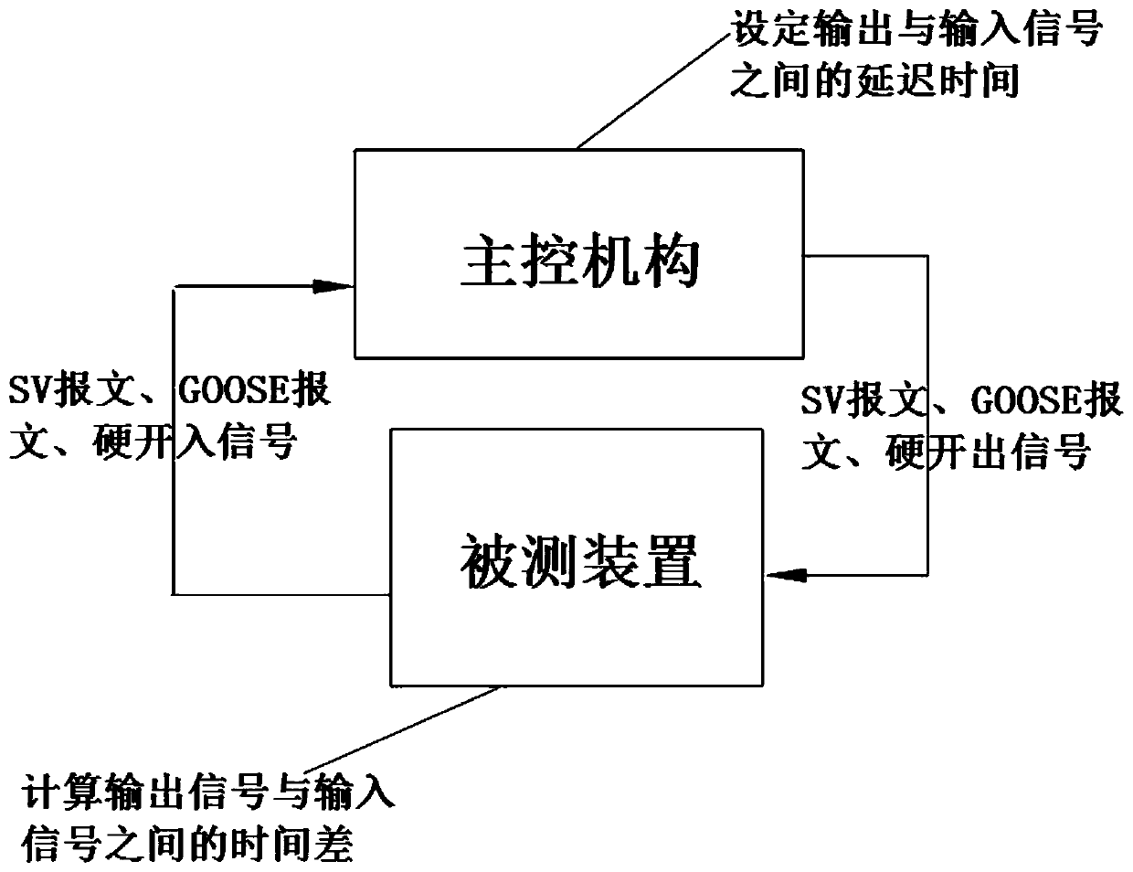
[0042] A method for testing the time measurement accuracy of a digital relay protection tester, such as figure 1 As shown, the device under test outputs SV message, GOOSE message or hard contact input signal and sends it to the main control mechanism. The main control mechanism collects the signal sent by the device under test and configures the SV message , GOOSE messages or hard-out signals are delayed and sent to the device under test.

[0043] In this embodiment, there are mainly four ways for the device under test to output and access signals, specifically, S1: the device under test outputs an SV message and receives back a GOOSE message, and calculates the time difference between output and access. The main control mechanism receives the SV message output by the device under test, records the receiving time, and outputs the GOOSE message to the device under test according to the delay time configured by the configuration module.

[0044] S2: The device under test output...

Embodiment 2

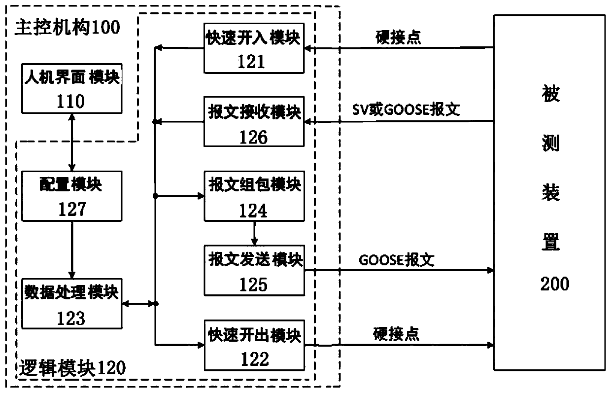
[0058] A system for testing the time measurement accuracy of a digital relay protection tester is realized by the test method in Embodiment 1. Such as image 3 As shown, a device under test 200 and a main control mechanism 100 are provided. The device under test 200 is connected to the main control mechanism 100. The main control mechanism 100 receives various signals output by the device under test 200, and responds to the corresponding signals according to the standard action time type. The signal is sent to the device under test 200 .

[0059] Specifically, the main control mechanism 100 can set the delay time between its own output and the input signal with high precision as a standard value for measuring the action time of the device under test 200 . Among them, the delay time setting range is 1us to 100s, the delay time setting error of SV and GOOSE messages is less than 20ns, and the delay time setting error of hard input and hard output is less than 20us.

[0060] In...

Embodiment 3

[0070] A system for testing the time measurement accuracy of a digital relay protection tester. Other structures are the same as in Embodiment 2, except that the device under test 200 uses a digital relay protection tester for testing.


PUM


Abstract

The invention discloses a system for testing the time measurement precision of a digital relay protection tester. A tested device and a main control mechanism are arranged. The tested device is connected with the main control mechanism; the tested device outputs an SV message, a GOOSE message or a hard contact input signal and transmits the SV message, the GOOSE message or the hard contact input signal to the main control mechanism; the main control mechanism collects signals transmitted by a tested device. And the SV message, the GOOSE message or the hard output signal is transmitted to the tested device in a delayed manner according to the delayed time configuration of the configuration module, so that the closed-loop testing device can be used for closed-loop testing of the time measurement accuracy of the digital relay protection tester of the power system, the testing environment is simplified, the manpower and equipment cost is reduced, and the working efficiency is improved.

Description

technical field [0001] The invention relates to the technical field of electric energy testing, in particular to a method and system for testing the time measurement accuracy of a digital relay protection tester. Background technique [0002] With the continuous development of smart substations and IEC61850, the application of digital relay protection and automation equipment is becoming more and more extensive. The outstanding feature is the support for receiving and sending SV messages and GOOSE messages. Due to the increasing digitalization of relay protection and automation equipment, traditional relay protection testers can no longer meet their main needs. Therefore, digital relay protection testers have emerged and are widely used. In order to verify the standard compliance of the digital relay protection tester and ensure that its time measurement function meets the application requirements, it is necessary to accurately test its time measurement accuracy. [0003] A...

Claims


Application Information

Patent Timeline
Patent Type & Authority Applications(China)
IPC IPC(8): G01R35/00
CPCG01R35/00
Inventor 陈光华黄岩郑蓬王朋飞贺春任春梅银庆伟穆小亮刘德森李翔贠雨含庞涛杨兴超赵华云
Owner XUCHANG KETOP DETECTION TECH CO LTD
Why Eureka
Try Eureka