
Industrial trackball mouse

A trackball, industrial technology, applied in instruments, electrical digital data processing, input/output process of data processing, etc., can solve problems such as failure to achieve control effect, trackball control failure, etc., achieve good control performance and easy installation , the effect of increasing the service life

Inactive Publication Date: 2020-04-03
奇科(清远)科技开发有限公司
View PDF1 Cites 0 Cited by
  • Summary
  • Abstract
  • Description
  • Claims
  • Application Information

AI Technical Summary

Problems solved by technology

[0002] Traditional desktop or notebook computers use a mouse or trackball device to control the cursor shift on the computer screen. Traditional industrial trackballs use bearings or zirconia beads as the support structure of the trackball. When the trackball is vertical or When the installation is tilted at a large angle, the trackball control will fail or the effective control effect will not be achieved.
[0003] Prior art, application number is CN200620149726.2 utility model patent, which discloses an optical trackball device, the optical trackball device includes a base, a top cover, a trackball, a light guide plate and an optical sensor The measuring element; wherein a plurality of balls are arranged in the bearing groove of the base, and the optical trackball device uses the balls to support the rolling of the trackball. Ineffective or unable to achieve effective control effect

Method used


Image

  • Industrial trackball mouse
  • Industrial trackball mouse
  • Industrial trackball mouse

Examples


Embodiment Construction

[0041] Embodiments of the present invention will be described in detail below.

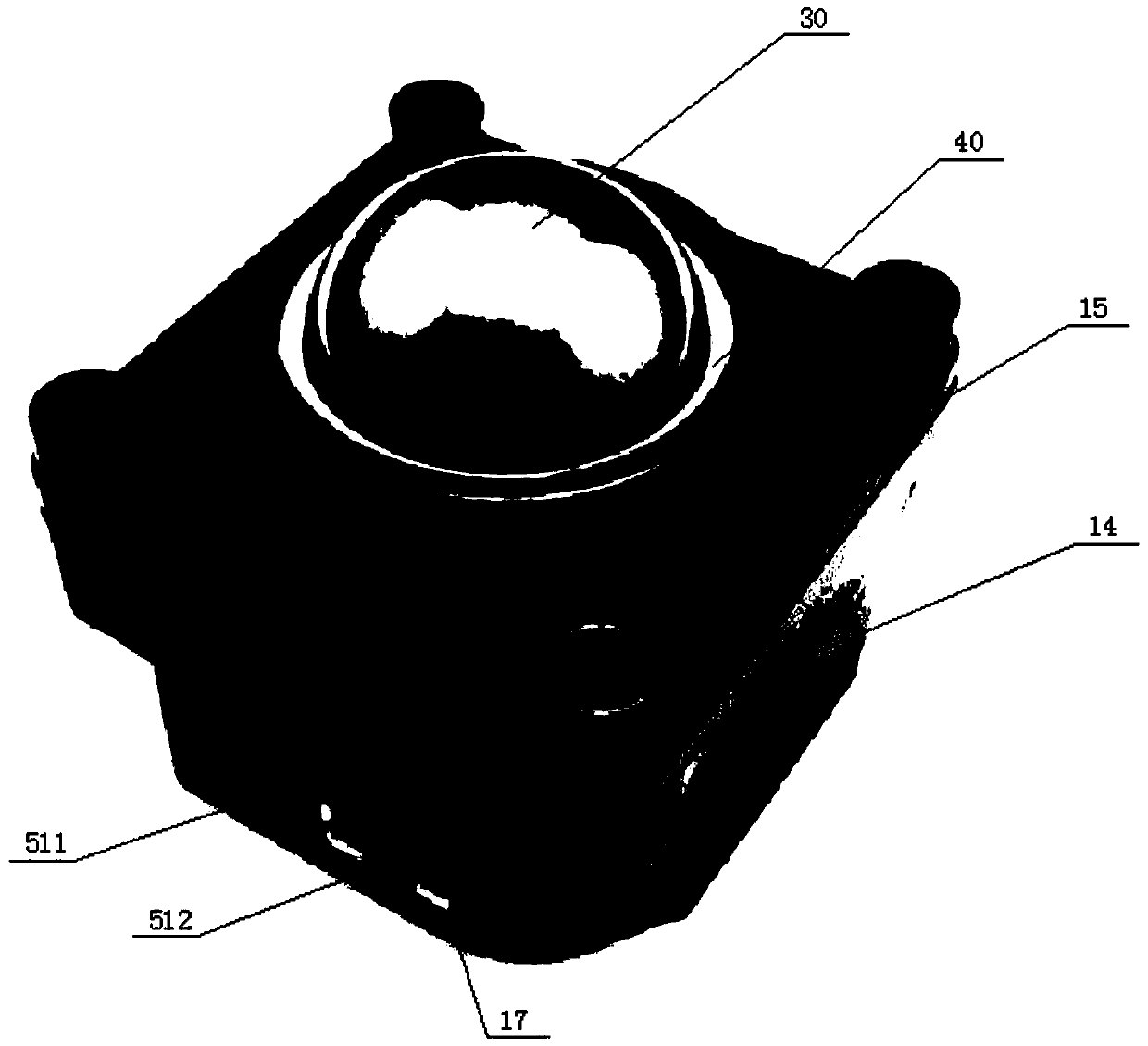
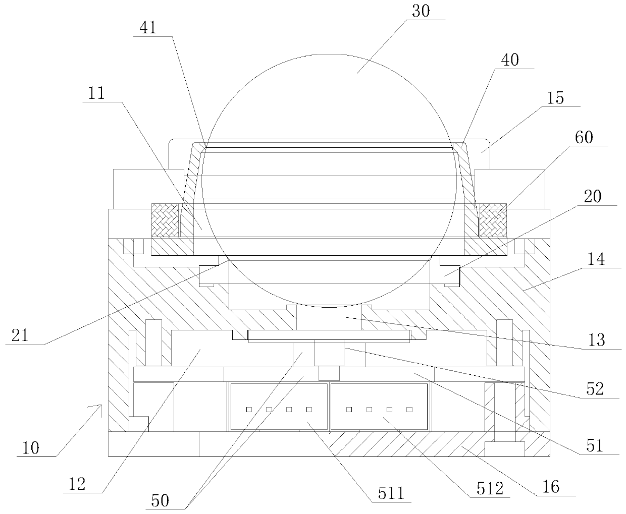
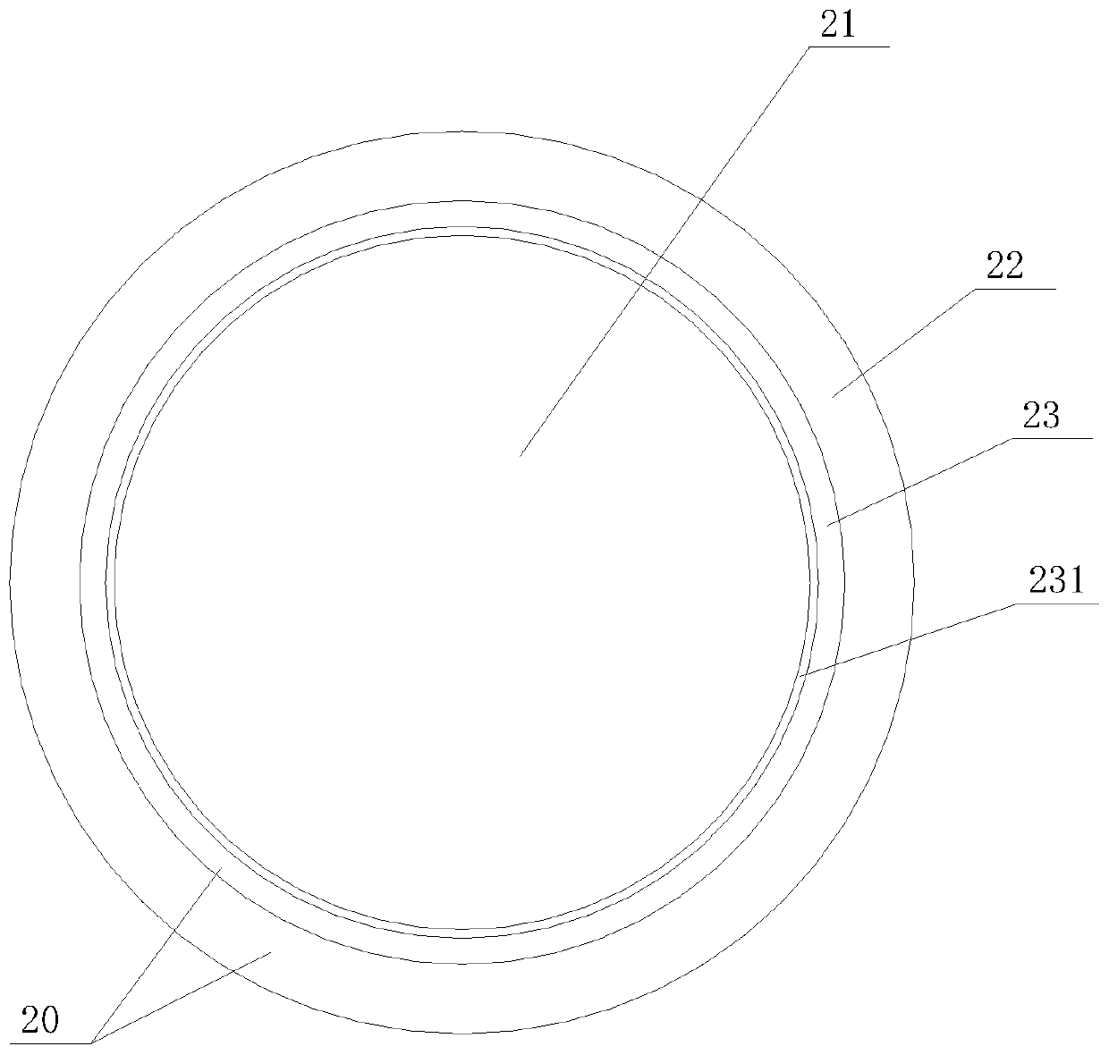
[0042] Such as Figure 1 to Figure 10As shown, the present invention provides an industrial trackball mouse, which includes a housing 10, a lubricating support ball seat 20, a trackball 30, a dustproof ring 40, and an optical sensing assembly 50. The housing 10 includes a ball accommodating cavity 11, Circuit accommodating chamber 12, light-transmitting hole 13, the middle of the bottom of ball accommodating chamber 11 communicates with circuit accommodating chamber 12 through light-transmitting hole 13; Lubricating support ball seat 20 has first round hole 21, the bottom end of trackball 30 The ball seat 20 is installed on the bottom of the ball accommodating cavity 11 through lubrication, and the bottom edge of the track ball 30 protrudes downwards from the first circular hole 21 of the ball seat 20 for the lubrication support; the dust seal 40 has a second circle Hole 41, the top of the trackb...


PUM


Abstract

The invention discloses an industrial trackball mouse. The industrial trackball mouse comprises a shell, a lubricating support ball seat, a trackball, a dustproof ring and an optical sensing assembly,the shell internally comprises a ball accommodating cavity, a circuit accommodating cavity and a light hole, and the ball accommodating cavity communicates with the circuit accommodating cavity through the light hole; the lubricating support ball seat is provided with a first round hole, the bottom end of the trackball is installed at the bottom of the ball accommodating cavity through the lubricating support ball seat, and the bottom end edge of the trackball protrudes downwards out of the first round hole of the lubricating support ball seat; the dustproof ring is provided with a second round hole, the top end of the trackball is installed at the top of the ball accommodating cavity through the dustproof ring, and the top end edge of the trackball protrudes upwards out of the second round hole of the dustproof ring; and the optical sensing assembly is installed in the circuit accommodating cavity. According to the industrial trackball mouse, the trackball is supported by a trackballseat to roll, and the position of the trackball is fixed by the dustproof ring, so that the trackball can roll at any mounting angle, and good control performance is provided for the trackball.

Description

technical field [0001] The invention relates to the field of computer input, in particular to an industrial trackball mouse. Background technique [0002] Traditional desktop or notebook computers use a mouse or trackball device to control the cursor shift on the computer screen. Traditional industrial trackballs use bearings or zirconia beads as the support structure of the trackball. When the trackball is vertical or When the installation is tilted at a large angle, the control of the trackball will fail or the effective control effect will not be achieved. [0003] Prior art, application number is CN200620149726.2 utility model patent, which discloses an optical trackball device, the optical trackball device includes a base, a top cover, a trackball, a light guide plate and an optical sensor The measuring element; wherein a plurality of balls are arranged in the bearing groove of the base, and the optical trackball device uses the balls to support the rolling of the trac...

Claims


Application Information

Patent Timeline
IPC IPC(8): G06F3/0354
CPCG06F3/03549
Inventor 唐琦
Owner 奇科(清远)科技开发有限公司
Learn More